Maintenance
85
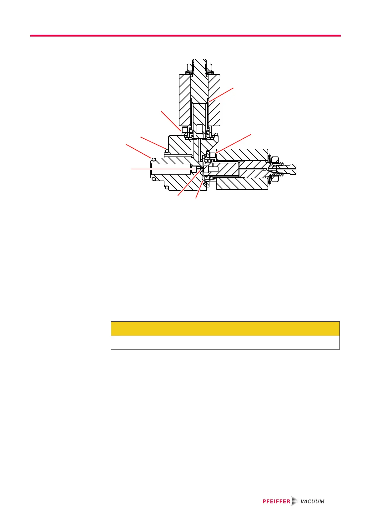
Figure 10-25 Valve Assembly
1 . . . . . . . . O-ring 9.25 x 1.78
2 . . . . . . . . Retaining Screw
3 . . . . . . . . Orifice
4 . . . . . . . . O-ring 12.42 X 1.78
5 . . . . . . . . Screw M3 X 6
6 . . . . . . . . Plunger with Spring and Seals
7 . . . . . . . . Plate
8 . . . . . . . . O-ring 18.77 X 1.78
18 Reinstall the gas inlet in the GSD 320 and connect the capillary.
19 Plug in the electrical connections of both valves.
20 Place insulation back inside the heater box, replace heater box cover, and front cover
to the GSD 320.
21 Plug in the mains power connector.
22 Put the GSD 320 into operation using the QUADERA software or the front panel.
23 Dispose of the replaced parts in accordance with local regulations.
CAUTION
Be careful not to mix up the valve cables.





 To Next Page