Maintenance
73
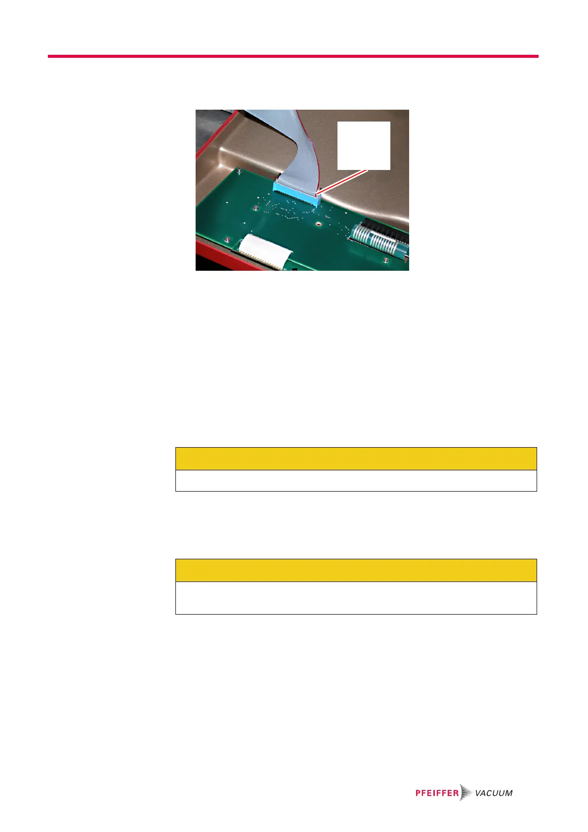
10 Connect the ribbon cable to the front panel. See Figure 10-12.
Figure 10-12 Re-install front panel ribbon cable
11 Re-install the front panel in the following manner:
11a Insert the top spring pins into the frame so they engage slightly in their mating
holes.
11b Engage the middle and bottom spring pins.
11c Gently tap around the edge of the panel to seat the spring pins in the frame.
12 If desired, re-install the front panel transport locking rod.
10.4 Inlet heater orientation instructions
To optimize orientation for the gas inlet for a given application, the capillary can be
oriented to the top, left, or right. Proceed as follows to re-orient the gas inlet.
1 Verify that the GSD 320 is shutdown in the proper manner.
2 Detach the capillary from the measurement point.
3 Remove mains power from the GSD 320.
Pin 1
Red stripe
oriented
as shown
CAUTION
Failure to follow this procedure can result in damage to the instrument.
CAUTION
Verify that the front panel transport locking rod has been removed. Refer to Removal of
transport locking parts on page 17.
 Loading...