List of figures
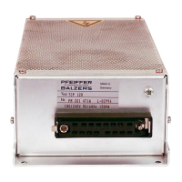
Fig. 1: Position of the stickers on the product 8
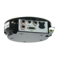
Fig. 2: TCP 350 connections and manual control elements 13
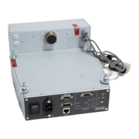
Fig. 3: Connecting turbopump to electronic drive unit 16
Fig. 4: Connection diagram for TCP350 with M12 accessory connection 17
Fig. 5: Connection diagram for TCP350 with M8 accessory connection 18
Fig. 6: Connection diagram for TCP350 with RJ45 accessory connection 19
Fig. 7: Rotation speed control mode pin 7 and pin 26 22
Fig. 8: Connection of the grounding cable to the TCP 350 25
Fig. 9: Cross-linking of turbopumps via RS-485 interface 28
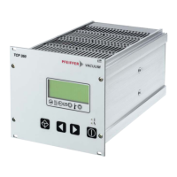
Fig. 10: LC-display, overview 35
Fig. 11: Schematic diagram of power characteristics, example of heavy gases
[P:027] = 0
40
Fig. 12: Rotation speed switch point active 41
Fig. 13: Dimensions TCP 350 53
List of figures
6/56
 Loading...