28 www.psterer.com
Drawings not to scale - for information only Size 3 | 3-S / Standard instructions wire screen / No. 040 371 001 (2014-05-08) i-01
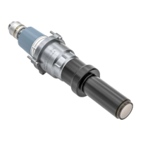
Fix contact ring onto the tension cone with the impact head.
The contact ring must no longer be able to rotate.
13 1
Recommended tools (see chapter 5.1, page 12):
▪ Impact head
Slide the retaining ring of the compression head back and x the half-
shells behind the thrust piece.
14 1
Do not damage the insulator.
VIII
Installation / Assembly
Squeeze the half-shells together and slide the retaining ring forward.
15 1
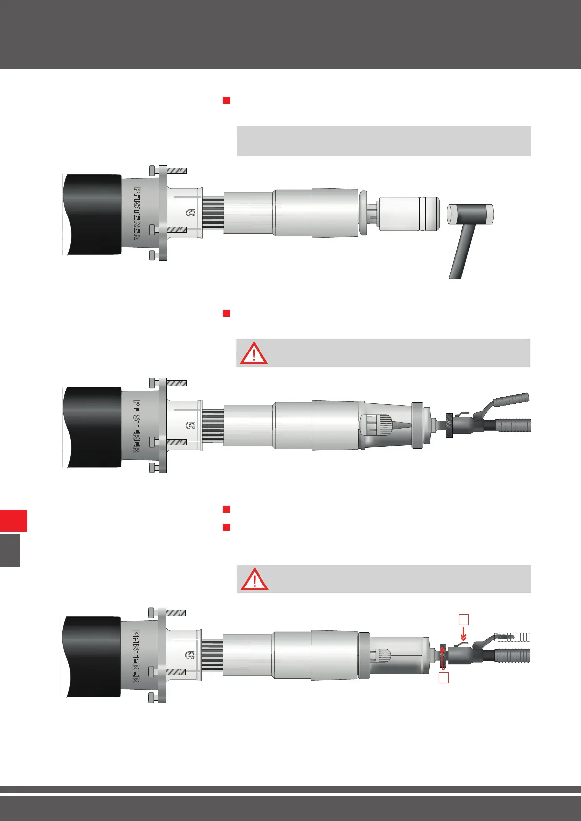
Turn the knurled wheel [1] of the hydraulic compression tool to the
right until the insert of the compression tool makes contact with the
contact ring.
16 1
Release the hydraulic compression tool before operating [2].
1
2