www.psterer.com 29
Drawings not to scale - for information only Size 3 | 3-S / Standard instructions wire screen / No. 040 371 001 (2014-05-08) i-01
2
VIII
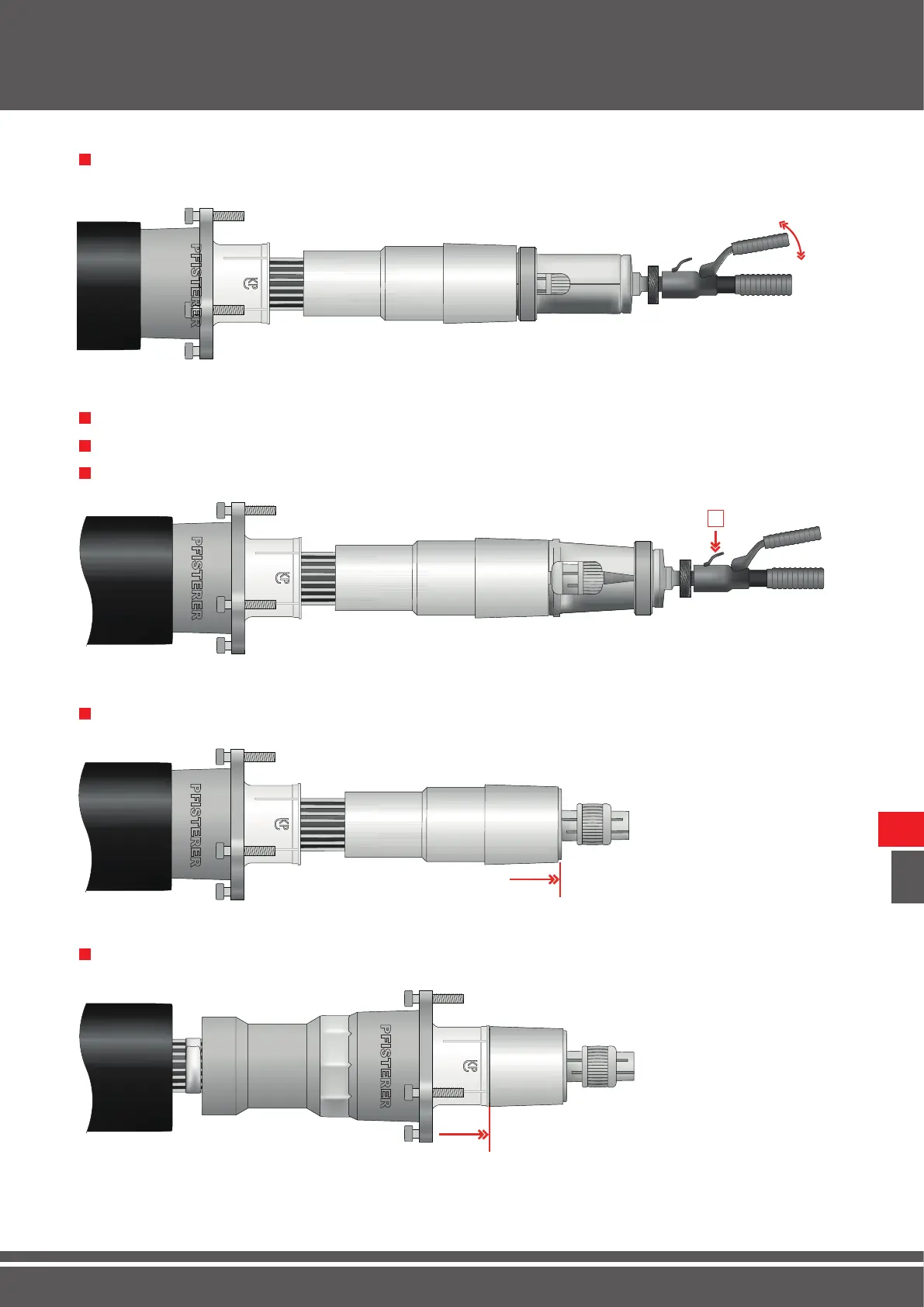
Installation / Assembly
Press the contact ring onto the tension cone with the hydraulic com-
pression tool until it reaches pressure.
17 1
Release the hydraulic compression tool [2].
18 1
Slide the retaining ring of the press head back and open the half-shells.
19 1
Remove the hydraulic compression tool.
20 1
Pull the insulating part ush against the thrust piece.
22 1
Slide the bell ange onto the insulating part.
21 1