20 | P a g e
4-20 mA Analog Transducer
Follow these steps to connect a 4-20 mA transducer:
Using the keypad, set the value of parameter SYSTEM CONFIG to 1 or 3 depending on the desired
mode of operation. See Table 16 and Section 6.5, System Configuration, for details.
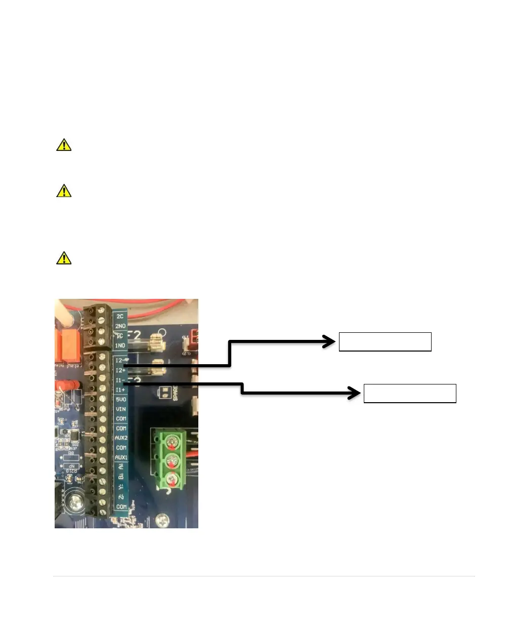
1. Connect the positive lead of the transducer to terminal I_1+.
2. Connect the negative lead of the transducer to terminal I_1-.
CAUTION: By default, AUX1 and AUX2 are programmed to be always in RUN mode.
Opening or closing AUX1 and AUX2 to COM will not affect drive operation. See parameters AUX1
SELECT and AUX2 SELECT to change this setting.
CAUTION: A 4-20 mA transducer with the parameter SYSTEM CONFIG set at 3 results in linear
speed control of the motor based on the analog signal from the transducer. This setting will not provide
control of a constant pressure water system. For constant pressure control with 4-20mA transducer,
refer to Section 6.5, System Configuration, and Section 7, Constant Pressure Water Systems, for more
information.
CAUTION: If the I_1+ and I_1- or the I_2+ and I_2- sensor cable is short circuited or if the sensor
fails, the drive will stop and indicate a fault, ANALOG 20 Ma FAULT. Disconnect input power to the
drive and fix the short circuit or replace the sensor.