19 | P a g e
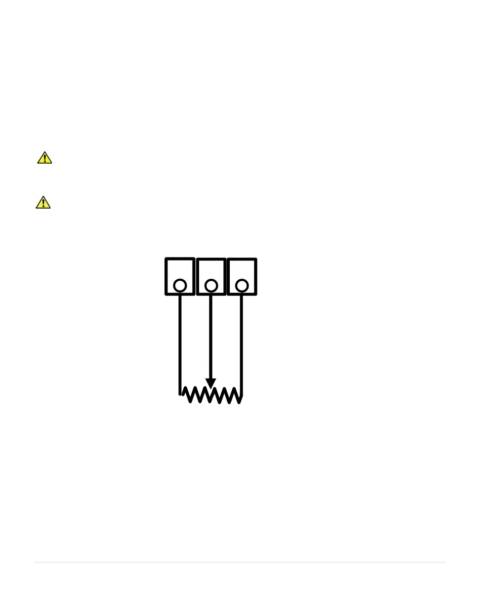
0-5 VDC Potentiometer
Follow these steps to connect a 0-5 VDC potentiometer to analog input:
Using the keypad, set the value of parameter SYSTEM CONFIG to 2. Refer to Table 16 or Section
6.5, System Configuration, for details.
1. Connect the negative lead of the potentiometer to Control Terminal COM
2. Connect the wiper terminal of the potentiometer to the V IN terminal.
3. Connect the positive lead of the potentiometer to the 5 VO terminal.
CAUTION: By default, AUX1 and AUX2 are programmed to be always in RUN mode.
Opening or closing AUX1 and AUX2 to COM will not affect drive operation. See parameters AUX1
SELECT and AUX2 SELECT to change this setting.
CAUTION: The resistance value of the transducer must be from 5,000 ohms to 20,000 ohms.
Resistance below 5,000 ohms will produce a high current in the circuit and may damage components in
the circuit.
Figure 17 - Connection Diagram for 0-5VDC Transducer (Potentiometer)