18 | P a g e
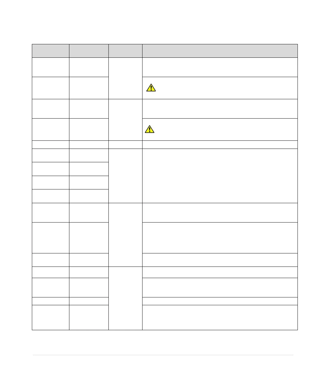
Table 8 - Control Terminal Ratings and Descriptions
0-30 VDC or
230 VAC,
10 A
Normally open relay controlled by the conditions set in Parameter
PROGRAM RLY 1. See Table 16, for instructions on programming
this relay.
Common terminal for 1NC and 1NO terminals.
CAUTION: This terminal is common only for 1NO and 1NC.
Do not use as common for other terminals.
0-30 VDC or
120VAC
<250mA
Normally open relay controlled by the conditions set in Parameter
PROGRAM RLY 2. See Table 16 for instructions on programming
this relay.
Common terminal for 2NC and 2NO terminals.
CAUTION: This terminal is common only for 2NO and 2NC.
Do not use as common for other terminals.
Common for all terminals except programmable relays.
Analog transducer connection for analog constant pressure or
proportional motor speed control from a current source. Refer to
Table 16 or Section 6.5, System Configuration, for details. See
Figure 18 for a connection diagram to control terminals.
5 VDC supply to provide power to a potentiometer. Refer to Table
16 or Section 6.5, System Configuration, for details. See Figure 16
for a connection diagram to control terminals.
Analog input for motor speed control for 0-5 VDC. Speed is relative
to scale of signal from 0 Hz to Maximum Frequency as set in
Adjustable Parameter menu (factory default 60 Hz). Connect the
wiper terminal of a potentiometer to this terminal. See Figure 17 for
a connection diagram to control terminals.
Common for 0-5 VDC. See Figure 17 for a connection diagram to
control terminals.
< 5 volts,
galvanically
isolated
Common terminal for AUX1 or AUX2
Programmable digital input. Commonly used for RUN/STOP
command. Controlled by parameter AUX1 SELECT. See Table 17,
Auto Restart Parameters, and Section 6.5 for details.
Common terminal for AUX1 or AUX2
Programmable digital input. Commonly used for RUN/STOP
command. Controlled by parameter AUX2 SELECT. See Table 17,
Auto Restart Parameters, and Section 6.5, System Configuration,
for details.