64 | P a g e
Programming Steps:
1. Use the keypad to navigate to the Main Menu item, CHANGE PARAMETER VALUES, then to
sub-menu LEAD LAG PUMP PARAMETERS. Scroll through parameters to find NUMBER
LAG PUMPS and use the arrow keys to set the number of auxiliary pumps in the system.
2. If necessary, adjust the remaining Lead/Lag parameters after reading the following description
of their functions, or after operating conditions dictate.
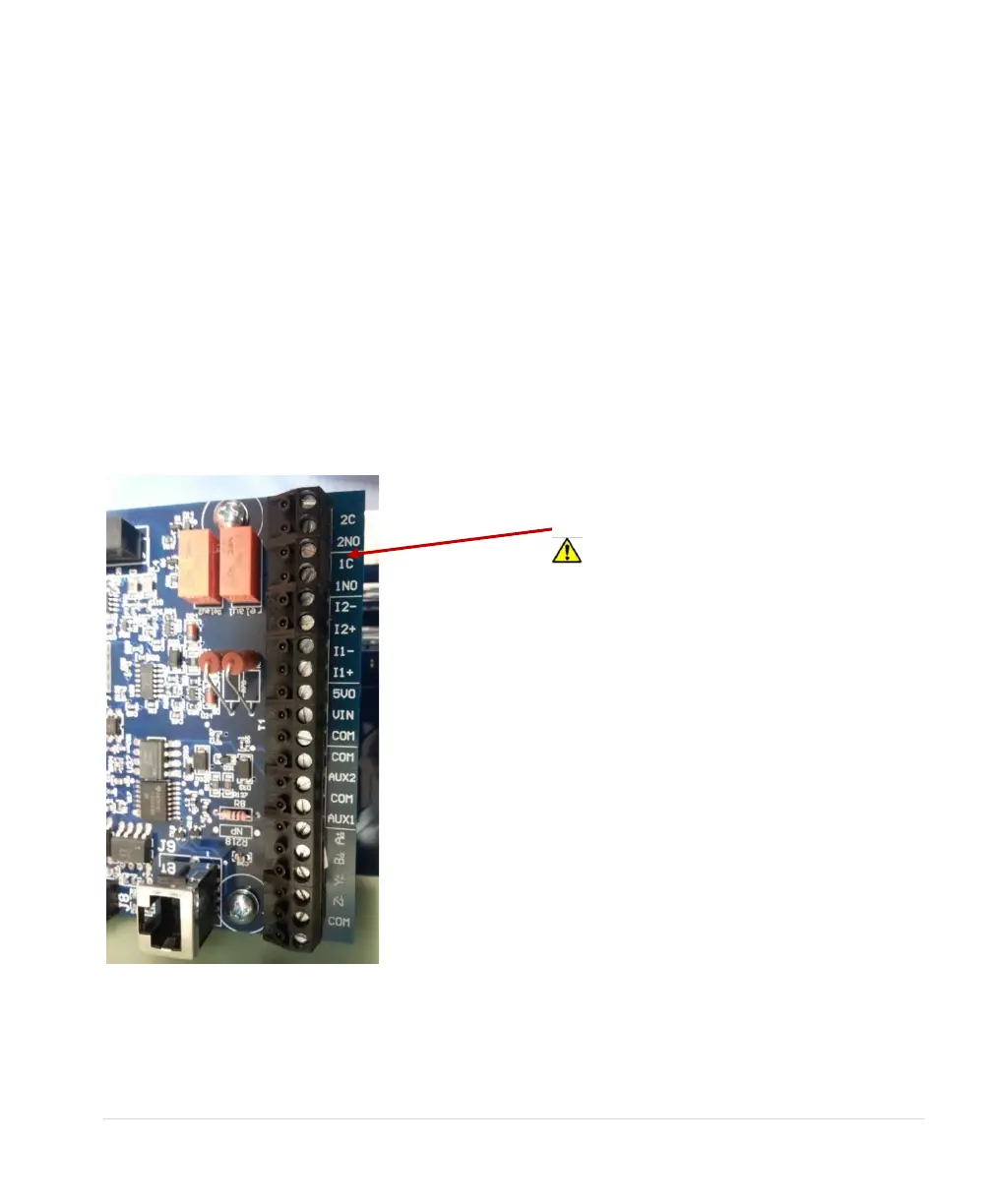
Lag pumps are turned on and off, or “staged” and “de-staged”, by programmable relays accessed
through the control terminals. The drive calls for lag pumps in ascending order, beginning with Relay 1.
See Figure 34, Programmable Relays for Lead/Lag Control, to locate the relays. Error! Reference
source not found., Lead/Lag Schematic, provides a wiring diagram.
Lead/lag parameters (See Table 18) are used to smoothly stage the pumps in and out, mitigating
pressure oscillation, short cycling and water hammer. When the main pump cannot maintain pressure,
the drive will stage in an auxiliary pump. The drive will de-stage the pump when flow increases
pressure beyond the control point.
Figure 34 – Programmable Relays for Lead/Lag Control
the coil on a magnetic motor starter will
likely cause damage to the relay and the
main control printed circuit board. Use of a
secondary control relay, such as an ice
cube relay, may be necessary to control
the lag pump motor starter.