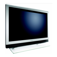
Do you have a question about the Philips 50PF9966 and is the answer not in the manual?
| aspect ratio | 16:9 |
|---|---|
| brightness | 900 cd/m² |
| contrast ratio | 1000:1 |
| diagonal screen size | 50 inch / 127 cm |
| viewing angle | 160 / 160 degree |
| panel resolution | 1366 x 768p |
| output power | 2x15W |
|---|---|
| sound system | Virtual Dolby Surround |
| built-in speakers | 4 |
| power consumption | 406 W |
|---|---|
| standby power consumption | 0.6 W |
| mains power | AC 110-120V (+/-10%) |
| ambient temperature | +5 -/+ 40 C |
| product weight | 58 kg |
|---|---|
| weight including packaging | 70 kg |
| color cabinet | Pearl White Silver |
Essential safety regulations and precautions to follow during and after repair.
Important warnings regarding electrostatic discharge, high voltage, and component handling during service.
Step-by-step instructions for removing various internal boards and panels from the chassis.
Detailed instructions for the safe removal and disassembly of the plasma panel and glass plate.
Procedures for reassembling the TV set after repair, ensuring all components and connections are correctly placed.
Description of Service Default Mode (SDM), Service Alignment Mode (SAM), and Customer Service Mode (CSM).
Troubleshooting guide for common picture and sound problems, referencing CSM settings.
Description of the ComPair service tool for diagnostics, pre-set management, and software upgrading.
Introduction to error codes, how to read and clear the error buffer, and explanations of common error types.
Procedure to display error codes via the front LED, useful when there is no picture.
Explanation of various protection mechanisms including I2C, OTC, and hardware protections.
Practical advice and troubleshooting tips for specific common issues, such as 3V3 supply problems.
Circuit diagram for the IF and I/O video processing circuitry.
Circuit diagram for the PICNIC IC, detailing its functions and connections.
Circuit diagram for the FEM IC, highlighting its motion estimation and memory features.
Circuit diagram for the Eagle IC, detailing upscaling, zooming, and color features.
Circuit diagram for the Columbus IC, covering comb filter and noise reduction functions.
Circuit diagram for the FBX supply board, showing power distribution.
Circuit diagram for the HOP control board, managing picture settings.
Circuit diagram for the OTC-Flash module, handling TV control and interface functions.
Circuit diagram for the audio demodulator IC, processing audio signals.
Circuit diagram for the Dolby Digital decoder IC, handling digital audio decoding.
Circuit diagram for the Dolby Pro Logic processor, managing surround sound.
Circuit diagram for the audio delay circuits, managing audio synchronization.
Circuit diagram for the main TV tuner, receiving RF signals.
Circuit diagram for the secondary tuner, used for specific features like PIP.
Circuit diagram for the DC/DC converter, showing power regulation.
Circuit diagram for the I/O 1 board, handling various input/output signals.
Circuit diagram detailing the connections for the I/O2 board.
Circuit diagram for the I/O3 board, managing input signal switching.
Procedures for software alignments, including LUMA GAIN, IF AFC, TUNER AGC, and BLEND INTENSITY.
Detailed description of the power supply units for SDI and FHP PDP displays, including changes in 2004.
Detailed explanation of the 3D Comb filter's operation, including signal types and modes (Bypass, Band-Pass-Notch, Median, Field, Frame).
Description of the Eagle IC's features: Vertical upscaler, Zoom, Interlacer, Horizontal upscaler, Panorama, LTI, Peaking, and Color Features.
 Loading...