Mechanical Instructions
EN 8 FTP2.2U AA4.
4.3 Assy/PWB Removal
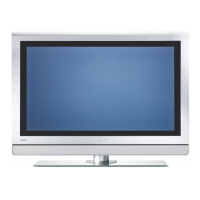
4.3.1 Metal Back Plate
Caution: Disconnect the AC Power (mains) cord before you
remove the metal back plate.
Figure 4-4 Metal back plate
1. Place the TV set upside down on a table top, using the
foam bars (see part "Foam Bars"). Caution: do not put
pressure on the display, but let the monitor lean on the
speakers or the Front cover.
2. Remove all T10 parker screws (1) from the top, centre, and
left and right sides of the back plate.
3. Remove all T10 tapping screws (2) from the bottom of the
back plate.
4. Remove the four "mushrooms" (3) from the back plate.
5. Lift the back plate from the set. Make sure that wires and
flat foils are not damaged during the back plate removal.
4.3.2 Rear Cover
Figure 4-5 Rear cover
1. Disconnect all four connectors (1) at the Ambient Light
Inverter that go to the Ambient Lights in the rear cover.
2. Remove all T10 parker screws (2) around the edges of the
rear cover.
3. Lift the rear cover from the set.
4.3.3 Ambient Light Panel
1. Disconnect all cables from the Ambient Light Inverter
panel.
2. Remove all mounting screws from the Ambient Light
Inverter panel.
3. Take out the Ambient Light Inverter panel.
4.3.4 Power Supply Panel
1. Disconnect all cables from the Power Supply panel.
2. Remove all mounting screws from the Power Supply panel.
3. Take out the Power Supply panel.
4.3.5 Audio Panel
1. Disconnect all cables from the Audio panel.
2. Remove all mounting screws from the Audio panel.
3. Take out the Audio panel.
4.3.6 Side I/O Panel
1. Disconnect the cable from the Side I/O panel.
2. Release the clamps and take out the Side I/O panel from
its bracket.
4.3.7 Top / Side Control
1. Remove the mounting screws from the Top / Side Control
panel bracket.
2. Disconnect the cable.
3. Release the clamps and take out the Top / Side Control
panel.
4.3.8 LED Panel
1. Disconnect all cables from the LED panel.
2. Remove the mounting screws from the LED panel.
3. Take out the LED panel.
4.3.9 Speakers
1. Remove all mounting screws.
2. After removing the cover plate, you can access the
speakers.
3. Be sure that the foam that makes the unit airtight is not
damaged.
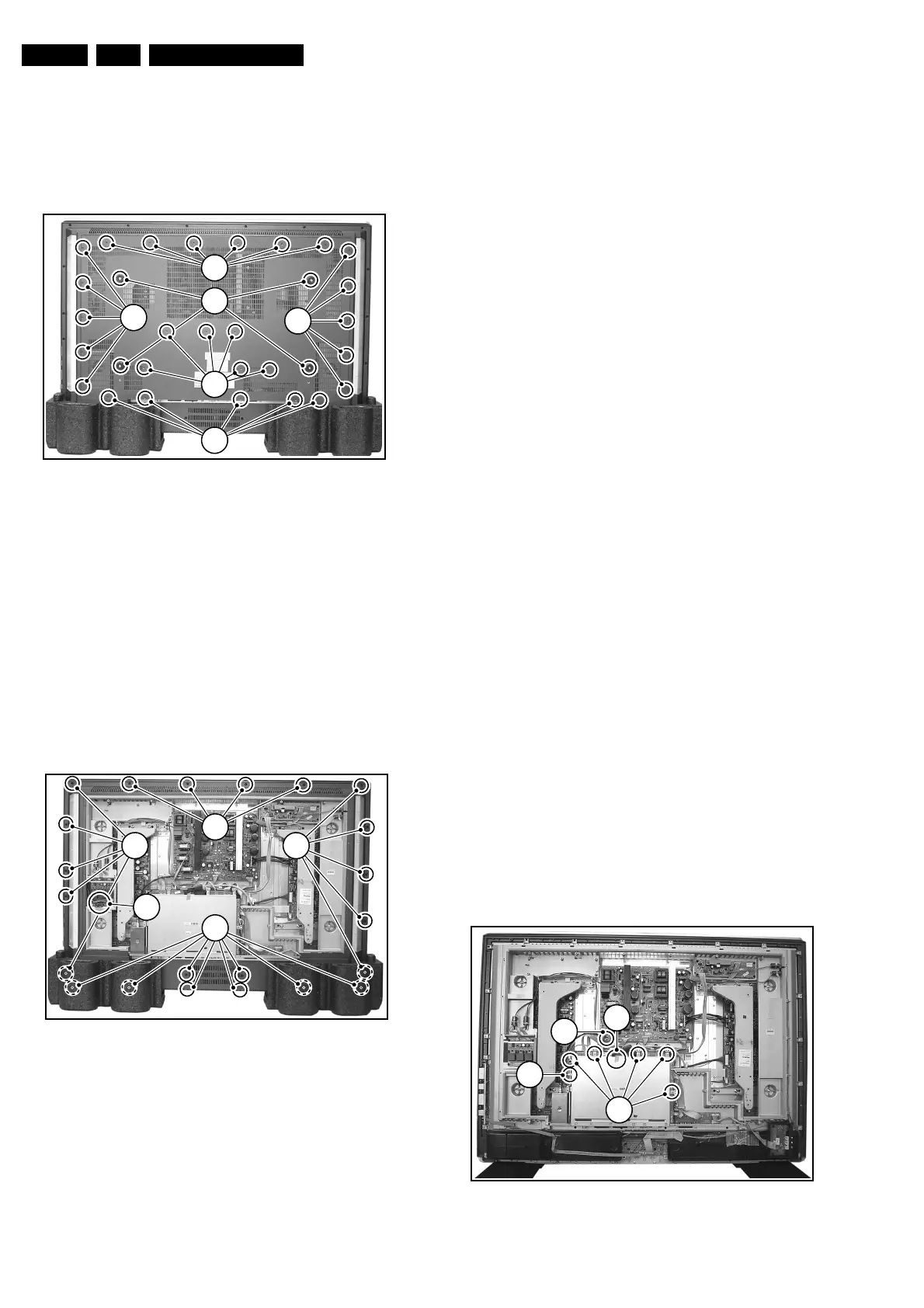
4.3.10 SSB
Figure 4-6 SSB top shielding
E_14650_003.eps
150604
1
2
1
1
1
3
E_14650_004.eps
150604
2
2 2
2
1
E_14650_006.eps
160604
2
1
2a
2b