Mechanical Instructions
EN 9FTP2.2U AA 4.
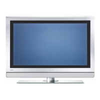
Figure 4-7 SSB (photo from FTL2.1)
1. Remove the LVDS fixing tape (1).
2. Remove all fixing screws (2).
3. Disconnect the grounding wire from the AC Power filter
(2a).
4. Shift, and lift the shielding at the top. The panel hinges at
the connector side.
Caution: do not damage the EMC shielding foam while
you remove the shielding.
5. Remove all connector fixation screws from the connector
plate.
6. Remove the mounting screws from the SSB (5).
7. Disconnect the LVDS cable (6).
8. Lift the SSB, disconnect all cables, and take out the SSB.
4.3.11 Ambient Lights
Figure 4-8 Ambient light
Ambient lights are located in the rear cover of the set.
1. Remove all mounting Ambient Light screws (1).
2. Unplug the connectors (mounted with double-sided tape)
(2).
3. Shift the Ambient light unit to the side (3) and take out the
unit.
4.4 Plasma Panel / Glass Plate (Dis)Assembly
Important: Be sure to work in a dust free environment during
the following activities. In addition, the use of (fabric) hand
gloves is advised.
4.4.1 Plasma Display Panel
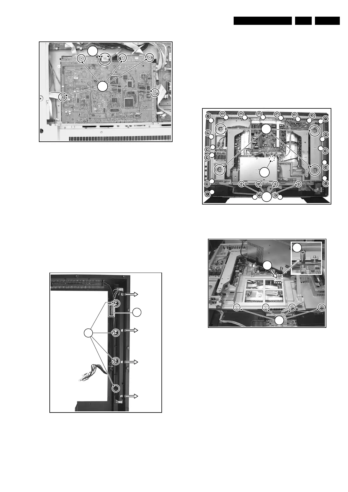
Figure 4-9 Plasma panel removal (photo from 42” FHP)
Figure 4-10 Hidden screw
Disassembly
1. Place the TV set face down on the foam bars. Place the
bars at the edges of the set so they will support the front
frame, and not only the glass plate!
2. Remove the four T25 screws (1) that hold the plasma
panel.
Note: In some models, the upper left T25 screw is hidden
under the Ambient Light Inverter panel. Remove this panel
to get access to it.
3. Remove the fifth T25 screw that is located near the SSB.
Note: In some models, this fifth screw is hidden under the
SSB. To get access, you have to remove the four T10
screws (2) that mount the "SSB connector plate" to the
frame. Then, lift the complete SSB unit away, so you can
remove the hidden screw (4).
4. Remove all T10 tapping screws around the frame (4).
5. Next step is to unplug the following connectors (see also
Wiring Diagram in chapter 6):
– AC Power plug on PSU.
E_14620_032.eps
130504
6
5
E_14650_008.eps
150604
3
3
3
3
1
2
E_14650_009.eps
170604
4
4
4
4
4
4
4
4
4
4
4
4
4
4
4
4
4
4
4
1
3
2
E_14650_010.eps
170604
4
2
5