Mechanical Instructions
EN 7FTP2.2U AA 4.
4. Mechanical Instructions
Index of this chapter:
1. Cable Dressing
2. Service Positions
3. Assy / PWB Removal
4. Plasma Panel / Glass Plate (Dis) Assembly
5. Set Re-assembly
Notes:
• Figures below can deviate slightly from the actual situation,
due to the different set executions.
• Follow the disassemble instructions in described order.
• Be aware that the internal (gold colored) frame is made of
conducting material. So, be cautious during electrical
measurements!
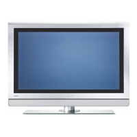
4.1 Cable Dressing
Figure 4-1 Cable dressing
4.2 Service Position
For easy servicing of this set, there are a few possibilities
created:
• The buffers from the packaging (see figure "Rear cover").
• Foam bars (created for service).
• Aluminium service stands (created for service).
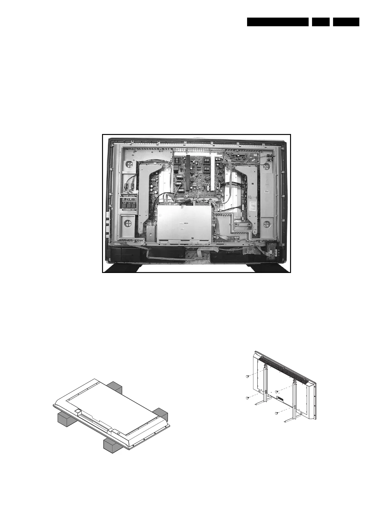
4.2.1 Foam Bars
Figure 4-2 Foam bars
The foam bars (order code 3122 785 90580 for two pieces) can
be used for all types and sizes of Flat TVs. By laying the TV
face down on the (ESD protective) foam bars, a stable situation
is created to perform measurements and alignments.
By placing a mirror under the TV, you can monitor the screen.
4.2.2 Aluminium Stands
Figure 4-3 Aluminium stands (MkI)
The new (MkII) aluminium stands (order code 3122 785
90690) can also be used to do measurements, alignments, and
duration tests. The stands can be (dis)mounted quick and easy
by means of sliding them in/out the "mushrooms".
Important: For (older) FTV sets without these "mushrooms", it
is obligatory to use the provided screws, otherwise it is possible
to damage the monitor inside!.
E_14650_002.eps
150604
E_06532_018.eps
170504
E_06532_019.eps
170504