Connection examples
106377_en_04 PHOENIX CONTACT 41 / 68
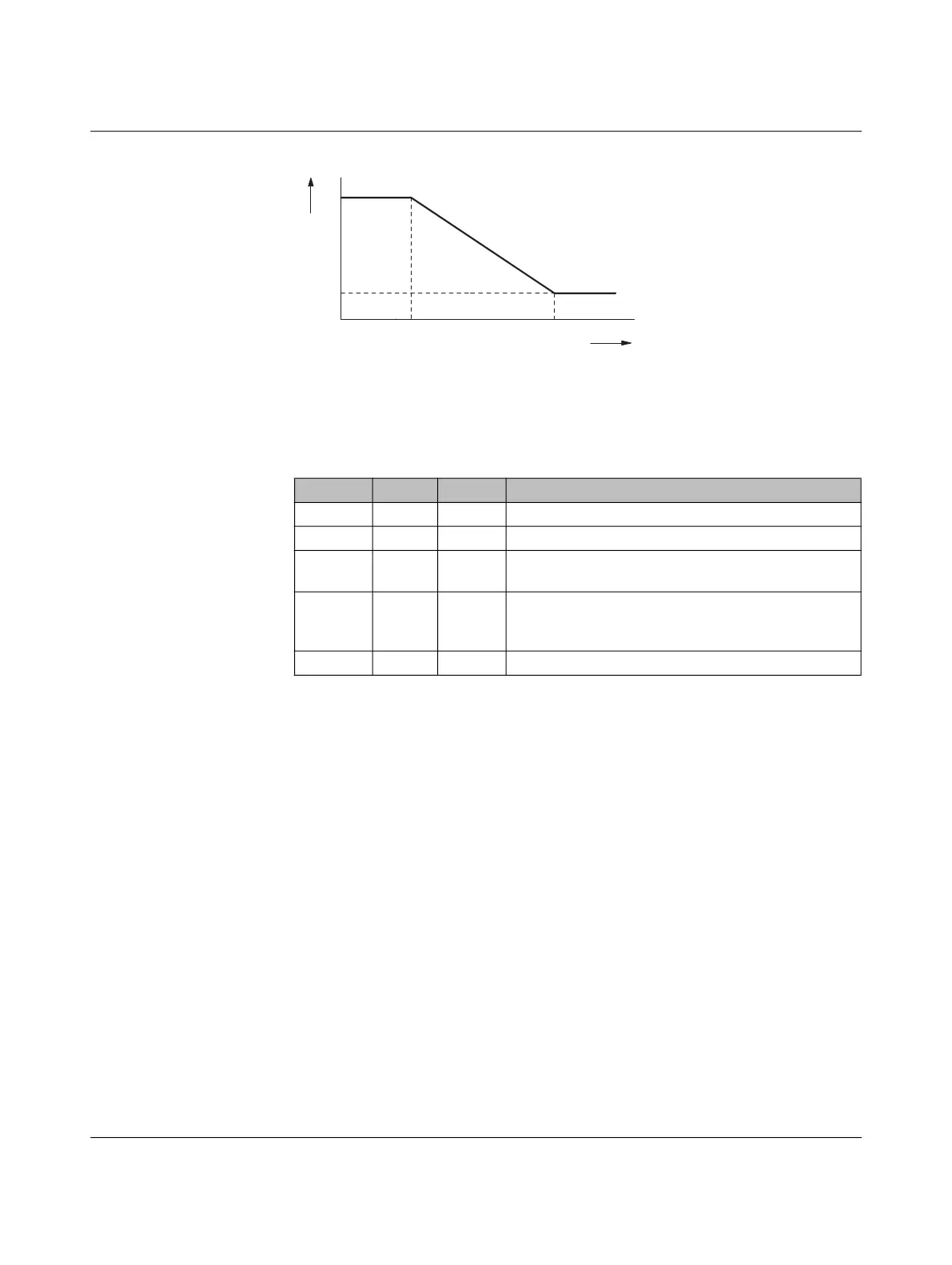
Figure 7-7 Charging current/voltage characteristic curve
The charging current/voltage characteristic curve describes the relationship between the
voltage that can be set at input CCR and the corresponding charging current that can be
used to charge the vehicle. In this way, the charging current can be controlled, e.g., for load
management. The characteristic curve can either have a positive or a negative gradient.
Table 7-1 shows an example of how the Modbus registers can be configured in order to con-
trol the charging current via the CCR function at the analog output.
Table 7-1 Device configuration example for charging current control
Address Value Unit Explanation
4006 0 – Contactor monitoring deactivated via CCR input
4012 2 – Analog evaluation of CCR input
4013 3000 mV Threshold value for charging with minimum current
strength
4014 10000 mV Threshold value for charging with maximum current
strength according to device configuration via
S1/DIP 5 + 6
4015 10 s Update time of charging current output