Connection examples
106377_en_04 PHOENIX CONTACT 43 / 68
Table 7-1 shows how the Modbus registers can be configured in order to monitor any weld-
ing of the charging contactor contacts. For charging contactor monitoring via input CCR,
charging current adaptation via input CCR must be deactivated.
If an error is detected, a signal can be created via one of the digital outputs. This signal can
be used to disconnect the voltage from the Infrastructure Socket Outlet using a redundant
switching element. To do so, one of the OUT, ERR, CHG, or CON outputs must be config-
ured to value “35” via the associated registers 5500 to 5503 (value “35” = “Charging contac-
tor monitoring triggered” (see Table 9-3).
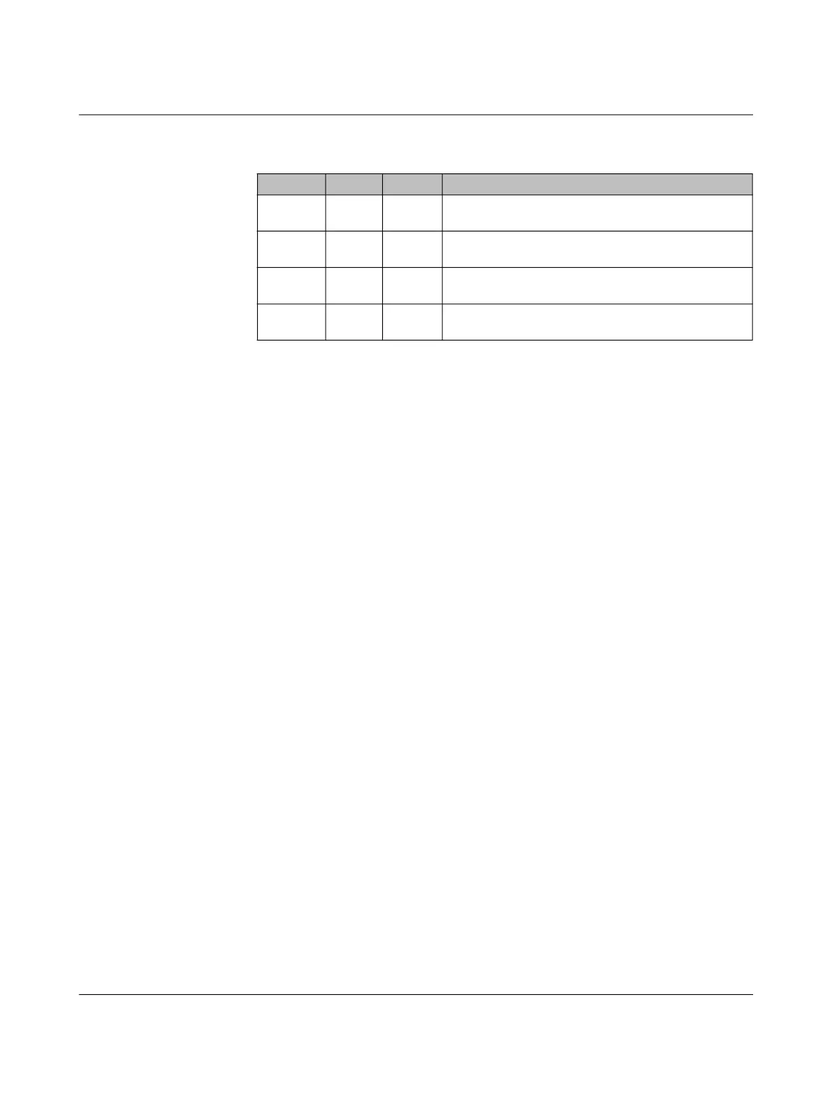
Table 7-2 Device configuration example for charging contactor monitoring
Address Value Unit Explanation
4012 0 – CCR function for charging current adaptation is deacti-
vated
4006 1 – Charging contactor monitoring via a force-guided N/C
contact at the CCR input
4007 200 ms Duration between switching off the contactor and eval-
uating the auxiliary contact
5500 35 – The output is set if charging contactor monitoring has
been triggered