ILC 1X1
32
PHOENIX CONTACT 8385_en_02
2.12 Communication paths
The communication path to the Inline controller must be determined before communication
with the Inline controller can take place.
The following communication paths are available on the Inline controller:
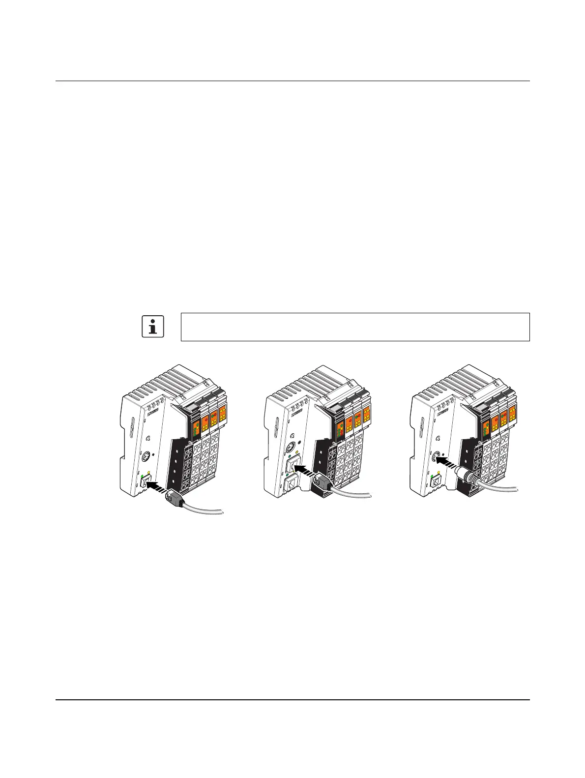
Figure 2-17 Communication paths: (A1/A2) Ethernet (B) PRG
ILC 131 ETH, ILC 151 ETH,
ILC 131 ETH/XC,
ILC 151 ETH/XC:
(A1) 1 x Ethernet 10/100Base-T(X)
ILC 171 ETH 2TX,
ILC 191 ETH 2TX:
(A2) 2 x Ethernet X2.1/X2.2: 10/100Base-T(X) (internally switched)
ILC 131 ETH, ILC 151 ETH,
ILC 171 ETH 2TX,
ILC 191 ETH 2TX,
ILC 131 ETH/XC,
ILC 151 ETH/XC:
(B) PRG The serial interface of your PC is directly connected to the Inline
controller (not for programming).
For additional information on using the serial interface (e.g., IP ad-
dress assignment), please refer to Section “Serial PRG interface -
function blocks” on page 35.
The Inline controller cannot be programmed via the RS-232 PRG interface.
AUTO
M
ATIO
NW
ORX
I
L
C
1
5
1
E
T
H
O
r
d
e
r
-
N
o
.
:
2
7
0
0
9
7
4
H
W
/
F
W
:
x
x
/
x
x
x
M
A
C
A
d
d
r
.
:
x
x
.
x
x
.
x
x
.
x
x
U
L
U
S
U
M
I1
I3
I2
I4
I6
I5
I8
I7
R
E
S
E
T
E
Q
2
Q
1
Q
3
Q
4
1
P
R
G
F
F
LNK
ACT
M
R
E
S
E
T
R
U
N
/
P
R
O
G
S
T
O
P
F
R
P
F
R
D
Y
F
A
I
L
A1
AUTO
M
ATION
W
ORX
I
L
C
1
5
1
E
T
H
O
r
d
e
r
-
N
o
.
:
2
7
0
0
9
7
4
H
W
/
F
W
:
x
x
/
x
x
x
M
A
C
A
d
d
r
.
:
x
x
.
x
x
.
x
x
.
x
x
U
L
U
S
U
M
I1
I3
I2
I4
I6
I5
I8
I7
R
E
S
E
T
E
Q
2
Q
1
Q
3
Q
4
1
P
R
G
F
F
LNK
ACT
M
R
E
S
E
T
R
U
N
/
P
R
O
G
S
T
O
P
F
R
P
F
R
D
Y
F
A
I
L
B
8385B011
E
Q
2
Q
1
Q
3
Q
4
UL
US
UM
FF
FR
I6
I5
I8I7
1
BSA
PF
I1
I3
I2
I4
1
RDY
FAIL
AUTOMATIONWORX
ILC 171 ETH 2TX
O
r
d
e
r
-
N
o
.
:
2
7
0
0
9
7
5
H
W
/
F
W
:
x
x
/
x
x
x
M
A
C
A
d
d
r
.
:
x
x
.
x
x
.x
x
.
x
x
R
E
S
E
T
X
1
X
2
.
1
X
2
.
2
P
R
G
L
N
K
L
N
K
A
C
T
A
C
T
M
R
E
S
E
T
R
UN
/PRO
G
S
T
O
P
A2
B
S
A
B
S
A
BF
SF



 To Next Page