Description of the Inline controller
8385_en_02 PHOENIX CONTACT 33
2.12.1 Ethernet
For connecting the Ethernet network, a standardized Ethernet interface is available on each
of the ILC 131 ETH, ILC 151 ETH, ILC 131 ETH/XC and ILC 151 ETH/XC Inline controllers.
Using the ILC 171 ETH 2TX and ILC 191 ETH 2TX Inline controllers, two standardized
Ethernet interfaces (X2.1/X2.2) are provided for connection to the Ethernet network.
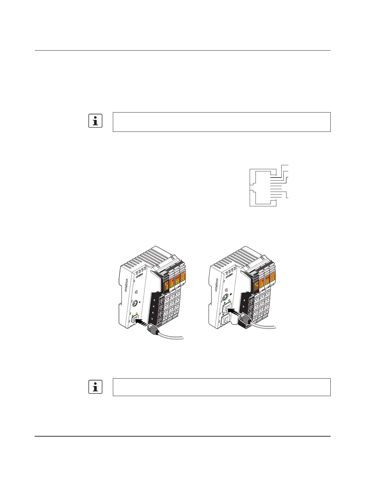
The Ethernet network is connected via RJ45 sockets.
The contact assignment of the interface is as follows:
Figure 2-19 Connecting the Ethernet cable to the Inline controller
A1: ILC 131 ETH, ILC 151 ETH, ILC 131 ETH/XC, ILC 151 ETH/XC
A2: ILC 171 ETH 2TX, ILC 191 ETH 2TX
Use an Ethernet cable which corresponds to CAT5 of IEEE 802.3 at least.
Observe the bending radii of the Ethernet cables used.
Transmit data + T + 1
Figure 2-18 Ethernet interface
Transmit data - T - 2
Receive data + R + 3
–4
–5
Receive data - R - 6
–7
–8
The interface is able to switch over the transmitter and receiver automatically (auto cross-
over).
RJ45
Pin 1
Pin 2
Pin 3
Pin 4
Pin 5
Pin 6
Pin 7
Pin 8
A
UTO
M
ATIO
NW
O
RX
I
L
C
1
5
1
E
T
H
O
r
d
e
r
-
N
o
.
:
2
7
0
0
9
7
4
H
W
/
F
W
:
x
x
/
x
x
x
M
A
C
A
d
d
r
.
:
x
x
.
x
x
.
x
x
.
x
x
U
L
U
S
U
M
I1
I3
I2
I4
I6
I5
I8
I7
R
E
S
E
T
E
Q
2
Q
1
Q
3
Q
4
1
P
R
G
F
F
LNK
ACT
M
R
E
S
E
T
R
U
N
/
P
R
O
G
S
T
O
P
F
R
P
F
R
D
Y
F
A
I
L
A1
8385B012
E
Q
2
Q
1
Q
3
Q
4
UL
US
UM
FF
FR
I6
I5
I8I7
1
BSA
PF
I1
I3
I2
I4
1
RDY
FAIL
AUTOMATIONWORX
ILC 171 ETH 2TX
O
r
d
e
r
-
N
o
.:
2
7
0
0
9
7
5
H
W
/
F
W
:
x
x
/
x
x
x
M
A
C
A
d
d
r
.
:
x
x
.
x
x
.
x
x
.
x
x
R
E
S
E
T
X
1
X
2
.
1
X
2
.
2
P
R
G
L
N
K
L
N
K
A
C
T
A
C
T
M
R
E
S
E
T
RU
N
/PRO
G
S
T
O
P
A2
B
S
A
BF
SF