Description of the Inline controller
8385_en_02 PHOENIX CONTACT 41
2.15 Digital inputs and outputs
There are eight 24 V DC inputs and four 24 V DC outputs.
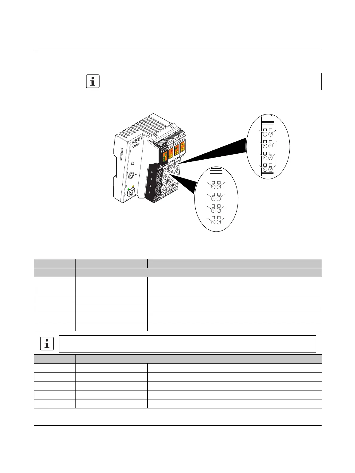
Figure 2-24 Assignment of terminal points of connectors 2 to 4
The descriptions for digital inputs and outputs apply to all the Inline controllers listed on
the inner cover page of this user manual.
AU
TO
M
AT
ION
W
ORX
IL
C
1
5
1
E
T
H
O
rd
e
r-N
o
.: 2
7
0
0
9
7
4
H
W
/F
W
: x
x
/x
x
x
M
A
C
A
d
d
r.: x
x.x
x
.xx
.x
x
UL
US
UM
I1
I3
I2
I4
I6
I5
I8I7
R
E
S
E
T
E
Q2
Q1
Q3
Q4
1
P
R
G
FF
L
N
K
A
C
T
M
R
E
S
E
T
R
U
N
/P
R
O
G
S
T
O
P
FR
PF
RDY
FAIL
8385B015
12
1
2
3
4
1
2
3
4
2 - 3
12
1
2
3
4
1
2
3
4
4
Table 2-3 Terminal point assignment
Terminal point Assignment Note
Connector 2 Output terminal points
1.1 Q1 Output 1
2.1 Q2 Output 2
1.2, 2.2 GND Ground connection for 2 and 3-conductor connection
1.3, 2.3 FE Functional earth ground for 3-conductor connection
1.4 Q3 Output 3
2.4 Q4 Output 4
Connector 3 Input terminal points
1.1 I1 Input 1
2.1 I2 Input 2
1.2, 2.2 24 V Supply voltage U
M
for 2 and 3-conductor connection
1.3, 2.3 GND Ground connection for 3-conductor connection
1.4 I3 Input 3
The outputs are supplied with 24 V DC from the segment supply (U
S
).



 To Next Page