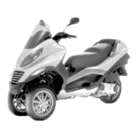
Hydraulic system layout
When tilting is locked, the geared motor activates
the hydraulic pump indicated in the photograph
and pressurises the circuit.
The pressurised oil reaches the distribution frame
"T" and the pressure sensor "A". Then, the pipes
branch out to reach the upper joints on the side
steering tubes.
Through the rigid-flexible pipes inside the side
steering tubes, the oil reaches the stem sliding
locking device placed parallel to the shock absorb-
er.
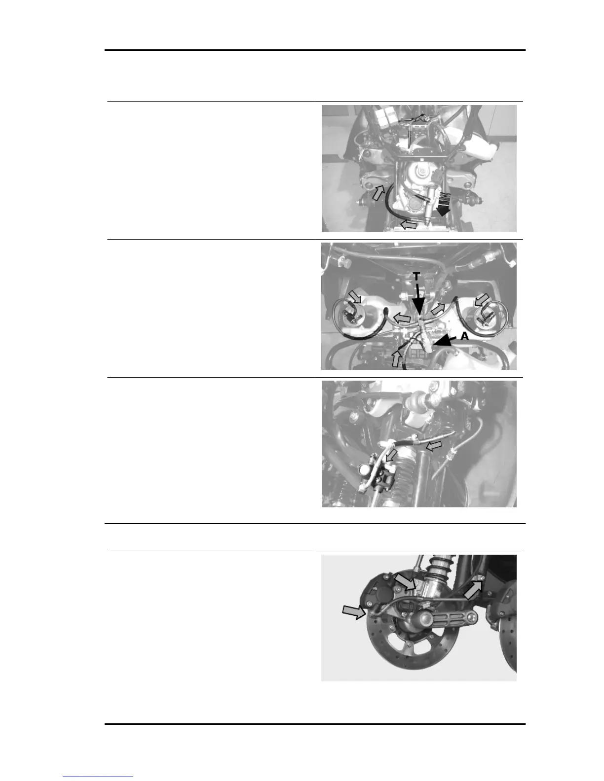
Steering tubes
Remove the brake calliper pipe retainers and the
hydraulic pipe fitting from the brake calliper making
sure there is a container to collect the brake fluid.
MP3 250 i.e. Suspensions
SUSP - 5