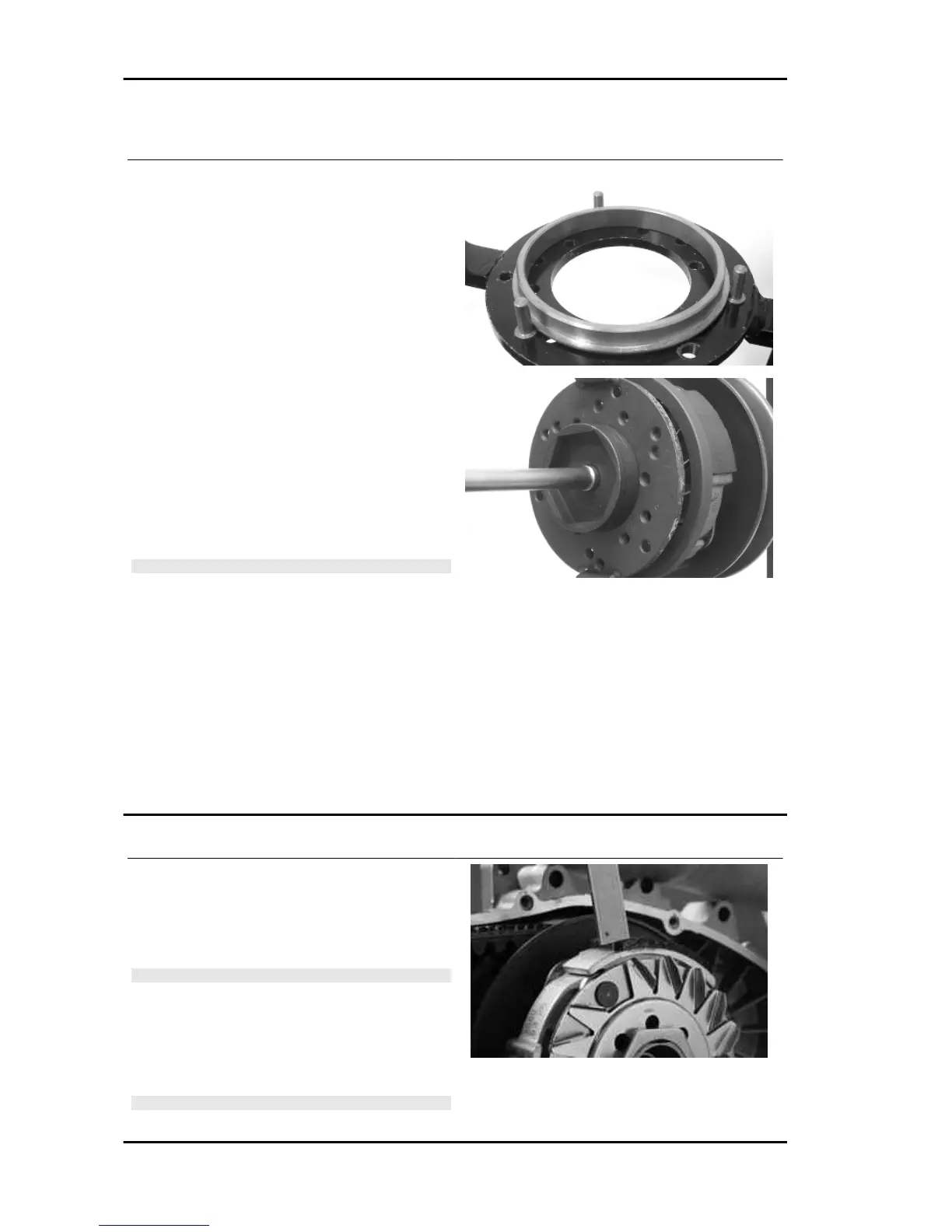
Removing the clutch
Fit the driven pulley spring compressor specific
tool with medium length pins screwed in position
«C» on the tool internal side.
- Introduce the adapter ring No. 11 with the cham-
fering facing the inside of the tool.
- Fit the driven pulley unit on the tool with the in-
sertion of the 3 pins in the ventilation holes in the
mass holder support.
- Make sure that the clutch is perfectly inserted into
the adapter ring before proceeding to loosen/tight-
en the clutch nut.
- Use the special 46x55 wrench component No. 9
to remove the nut fixing the clutch in place.
- Dismantle the driven pulley components (Clutch
and spring with its plastic holder)
CAUTION
THE TOOL MUST BE FIRMLY FIXED IN THE
CLAMP AND THE CENTRAL SCREW MUST BE
BROUGHT INTO CONTACT WITH THE TOOL.
EXCESSIVE TORQUE CAN CAUSE THE SPE-
CIFIC TOOL TO BUCKLE.
Specific tooling
020444Y011 adapter ring
020444Y009 46x55 Wrench
020444Y Tool for fitting/ removing the driven
pulley clutch
Inspecting the clutch
- Check the thickness of the clutch mass friction
material.
- The masses must not show traces of lubricants;
otherwise, check the driven pulley unit seals.
N.B.
UPON RUNNING-IN, THE MASSES MUST EX-
HIBIT A CENTRAL CONTACT SURFACE AND
MUST NOT BE DIFFERENT FROM ONE AN-
OTHER.
VARIOUS CONDITIONS CAN CAUSE THE
CLUTCH TO TEAR.
CAUTION
Engine MP3 250 i.e.
ENG - 6