Characteristic
clutch bell inspection: Limit eccentricity.
Admissible limit eccentricity: 0.15 mm
Removing the clutch
Clutch removal (125 cm³ H2O)
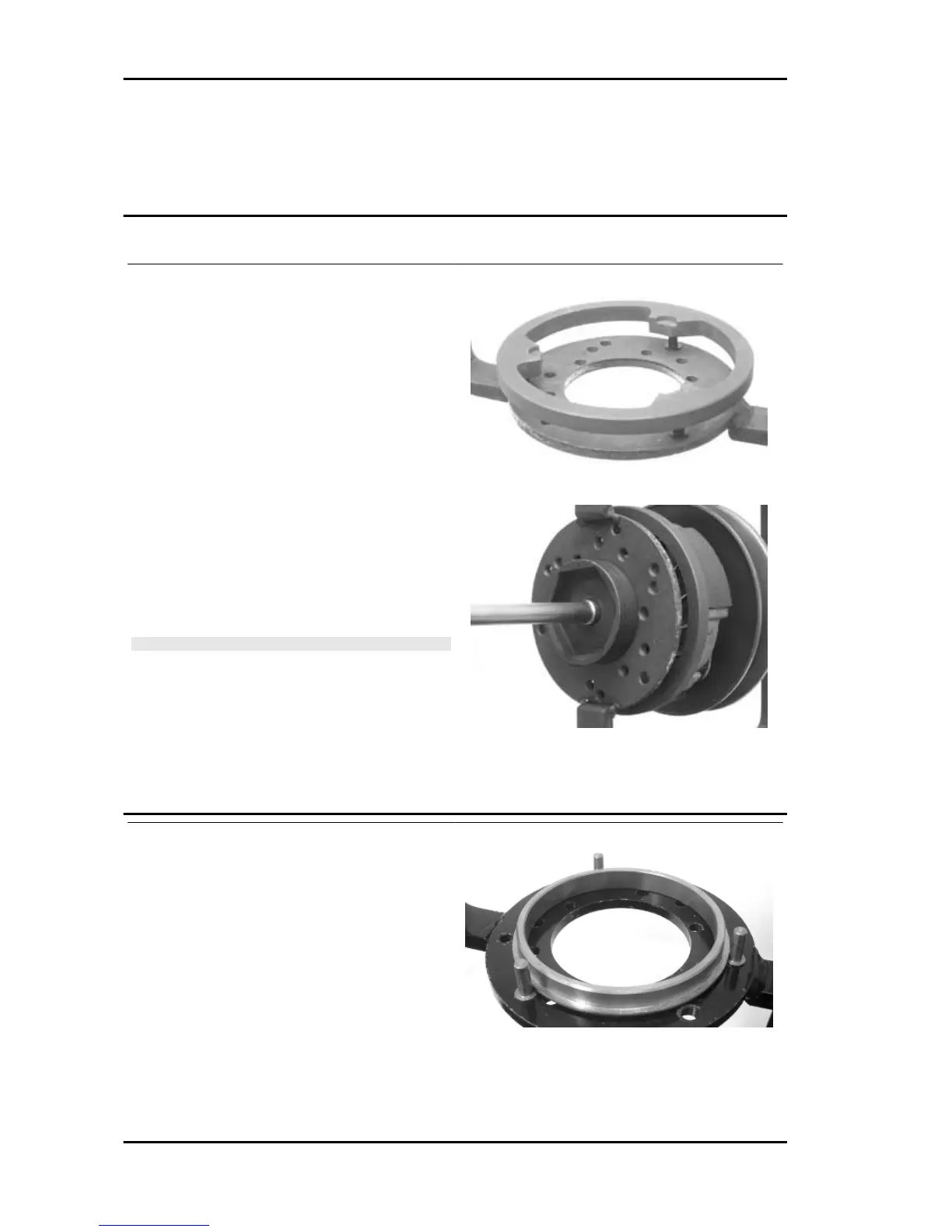
Fit the driven pulley spring compressor specific
tool with medium length pins screwed in position
F from the tool internal side.
- Insert the adapter ring 8 in the pins.
- Assemble the driven pulley unit on the tool intro-
ducing the rivets heads in the adapter ring.
- Make sure that the clutch is perfectly inserted into
the adapter ring before proceeding to loosen/tight-
en the clutch nut.
- Use the special 46x55 wrench component n°9 to
remove the nut fixing the clutch in place.
- Separate the driven pulley components (Clutch,
fan and spring with plastic fitting).
CAUTION
THE TOOL MUST BE FIRMLY FIXED IN THE CLAMP AND
THE CENTRAL SCREW MUST BE BROUGHT INTO CON-
TACT WITH THE TOOL. EXCESSIVE TORQUE CAN CAUSE
THE SPECIFIC TOOL TO BUCKLE.
Specific tooling
020444Y009 46x55 Wrench
020444Y010 adapter ring
Fit the driven pulley spring compressor specific
tool with medium length pins screwed in position
«C» on the tool internal side.
- Introduce the adapter ring No. 11 with the cham-
fering facing the inside of the tool.
- Fit the driven pulley unit on the tool with the in-
sertion of the 3 pins in the ventilation holes in the
mass holder support.
- Make sure that the clutch is perfectly inserted into
the adapter ring before proceeding to loosen/tight-
en the clutch nut.
Engine B 125-250
ENG - 108