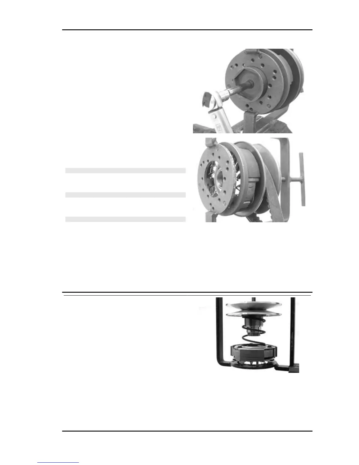
- Fully preload the spring.
- Apply the clutch lock nut and tighten it to the
specified torque using the specific 46x55 spanner.
- Loosen the tool clamp and insert the belt accord-
ing to its direction of rotation.
- Lock the driven pulley again using the specific
tool.
- Preload the clutch return spring with a traction/
rotation combined action until it reaches the pul-
leys maximum opening and place the belt on the
minimum rolling diameter.
- Remove the driven pulley /belt unit from the tool.
N.B.
FOR DESIGN REASONS, THE NUT IS SLIGHTLY ASYM-
METRIC; THE FLATTEST SURFACE SHOULD BE MOUN-
TED IN CONTACT WITH THE CLUTCH.
N.B.
DURING THE SPRING PRELOADING PHASE, BE CARE-
FUL NOT TO DAMAGE THE PLASTIC SPRING STOP AND
THE BUSHING THREADING.
N.B.
AN EXCESSIVE QUANTITY CAN DAMAGE THE CLUTCH
OPERATION.
Specific tooling
020444Y011 adapter ring
020444Y009 46x55 Wrench
Locking torques (N*m)
Clutch unit nut on driven pulley 55 ÷ 60
- Support the driven pulley spring compressor ap-
propriate tool with the control screw in vertical axis.
- Arrange the tool with the medium length pins
screwed in position "C" on the inside.
- Introduce the adapter ring 11 with the chamfering
facing upwards.
- Insert the clutch on the adapter ring.
- Lubricate the end of the spring that abuts against
the servo-system closing collar.
- Insert the spring with its plastic holder in contact
with the clutch.
- Insert the driving belt into the pulley unit accord-
ing to their direction of rotation.
B 125-250 Engine
ENG - 117
 Loading...