DT2010148-04
5.4 INSTALLING ThE y CONNECTOR (OPTIONAL)
•The ducting of heat to adjoining rooms is at the user’s discretion
according to requirements.
•The Y connector, designed to double hot air delivery, may be tted
onto one or both fans at the time the stove is installed.
•If just one Y connector is used, it is more convenient to t it onto the
right fan [1] (as seen from the rear). If two Y connectors are to be
used, rst work on the left fan [2] and then on the right [1] (as seen
from the rear Fig. 46).
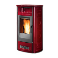
To install, proceed as follows:
- remove the side ceramic panels and the rear panel of the stove;
- uncoil the hose from the appropriate fan outlet by loosening the clip
that holds it in place (Fig. 47);
- cut off approx. 2” / (5 cm) of hose (Fig. 48);
- t the hose to the Y connector using the clip provided in the kit (Fig.
49);
- t the Y connector to the fan outlet using the screws provided in the
kit (Fig. 50);
- t the second hose to the Y connector using the clip provided in the
kit (Fig. 51);
- repeat steps 2 ÷ 6 for the other fan if two Y connectors are being
used;
- remove the knockout from the rear panel and insert the ducting
through the hole that has been created (Fig. 52);
- ret the rear panel and the side ceramic panels;
- move the stove closer to the wall (Fig. 53) and, using the clips provided
in the kit, x the two hoses to the walled ducting ttings (Fig. 54);
- put the stove in its nal location, complying with the minimum
safety distances (see par. 1.6).
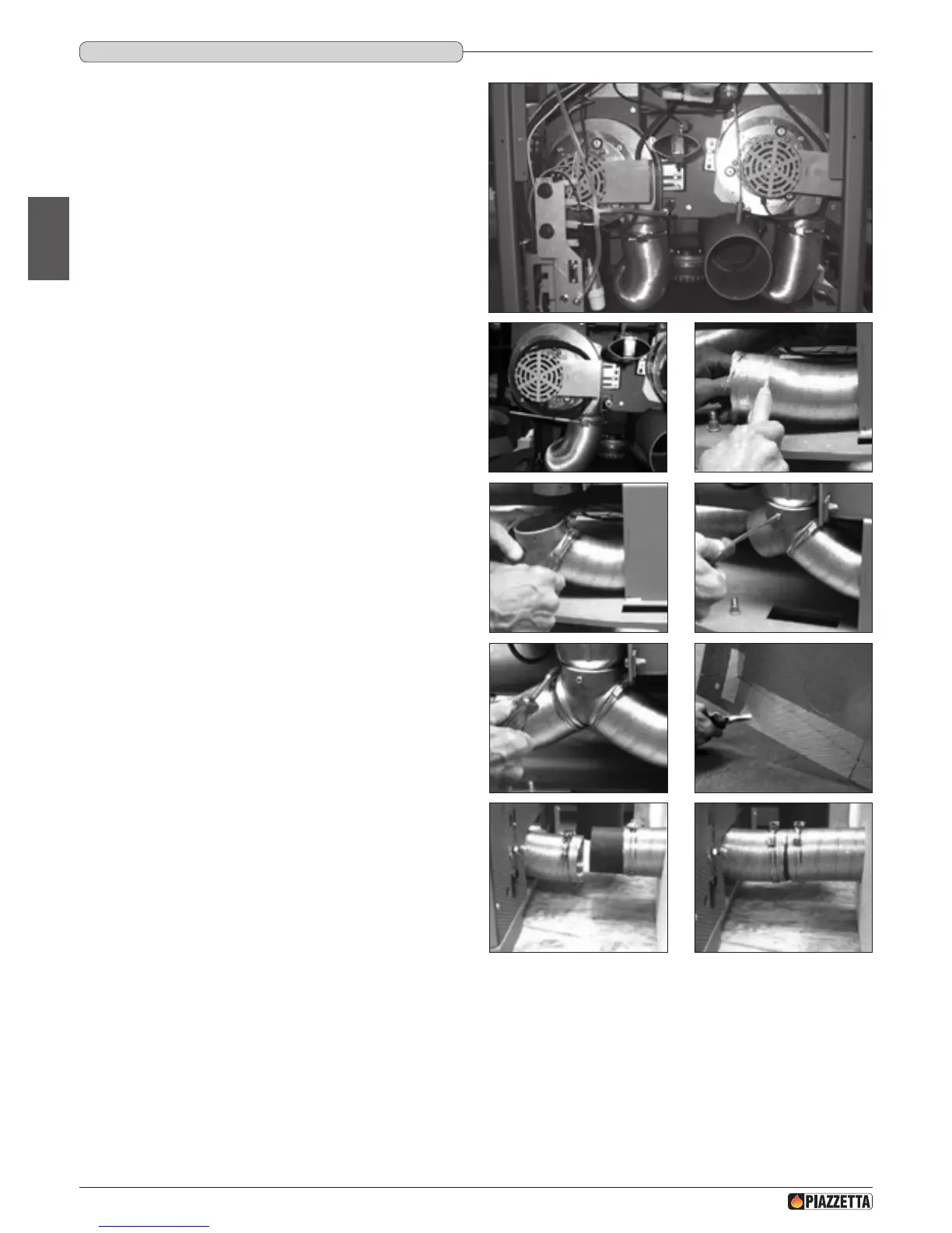
FAN 2
FAN 1
Fig. 46
Fig. 47 Fig. 48
Fig. 49 Fig. 50
Fig. 51 Fig. 52
Fig. 53 Fig. 54
H07028100/DT2000970 – 01
24
English
DT2030229-01
DT2031048-00 DT2030230-00
DT2030175-00 DT2030232-00
DT2030178-00 DT2030233-00
DT2030180-00 DT2030181-00