OPERATING MANUAL PSEN op4F/H-A series
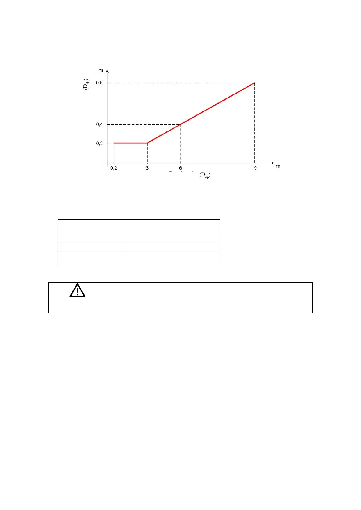
The following graphic shows the distance from the interfering devices (D
do
), based on the
operating range (D
op
) of the pair (TX A – RX A).
Fig. 12
For
the purpose of simplification, the table below states the values of the minimum safety
distances required for installation, with reference to some operating ranges.
Minimum safety distance
(m)
WARNING: The interfering transmitter (TX B) must be positioned at
the same distance D
do
, as calculated above,
from the other transmitter TX A is shorter than from the receiver
devices of the same type
 Loading...

