EasyManuals Logo

Pilz PSEN op4F-A Series User Manual

Pilz PSEN op4F-A Series
89 pages
To Next Page IconTo Next Page
To Previous Page IconTo Previous Page
Page #26 background imageLoading...
Page #26 background image
OPERATING MANUAL PSEN op4F/H-A series
PSENopt Advanced RX Blanking
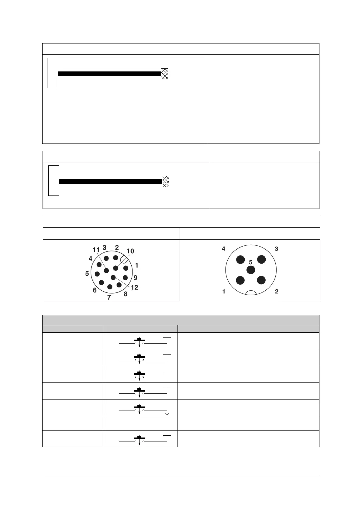
18 pin
M12 12 pin
M12 12-Pin:
1. 24 V (brown)
2. 0 V (blue)
3. RESET/RESTART/ALIGN (white)
4. TEACH IN (green)
5. OSSD2 (pink)
6. EDM (yellow)
7. NC (black)
8. OSSD1 (grey)
9. TOLERANCE (red)
10. LAMP (purple)
11. NC (grey-pink)
12. EARTHING (red-blue)
PSENopt Advanced TX
18 pin
M12 5 pin
M12 5-Pin:
1. 24 V (brown)
2. TEST (white)
3. 0 V (blue)
4. EARTH (black)
5. REDUCED RANGE (grey)
Assignment of M12 connector
12-pin
5-pin
PSENopt Advanced RX Muting
CONNECTION
LINE
BEHAVIOUR
RESET
24Vdc
IN line
N.O.
Is connected when in disabled state the
RESET/RESTART/ALIGN button is operated
RESTART
24Vdc
IN line
N.O.
Is connected when during operation the
RESET/RESTART/ALIGN button is operated
ALIGNMENT
24Vdc
IN line
N.O.
Has to be set to 24 V DC at startup
OVERRIDE 1
24Vdc
IN line
N.O.
Is connected when Override is active during
operation
OVERRIDE 2
IN line
N.O.
No voltage during operation
EDM
See section 7.4 for
connections
Must be non-equivalent to OSSD during operation
with EDM enabled
MUTING
DEACTIVATION
24Vdc
IN line
N.O.
Muting is disabled when connecting
26
1003067-EN-04

Table of Contents

Questions and Answers:

Question and Answer IconNeed help?

Do you have a question about the Pilz PSEN op4F-A Series and is the answer not in the manual?

Pilz PSEN op4F-A Series Specifications

General IconGeneral
BrandPilz
ModelPSEN op4F-A Series
CategorySafety Equipment
LanguageEnglish

Related product manuals