OPERATING MANUAL PSEN op4F/H-A series
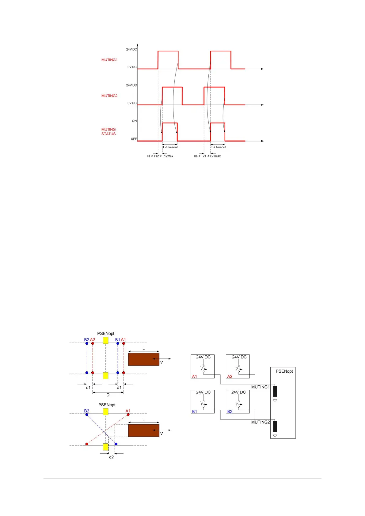
Fig. 42 – T muting timings
The s
ensors labelled A1/A2 are connected to the muting input (MUTING1) and the sensors
labelled B1/B2 are connected to the MUTING2 input. Sensors ending in “1” are on the same
side of the light curtain and therefore on the opposite side to the sensors ending in “2”.
“D
” stands for the distance at which the sensors A1/A2 or B1/B2 must be installed and
depends on the package length (L):
D < L
“d1”
stands for the maximum distance required between the muting sensors and depends on
the package speed (V):
d1
max
[cm] = V [m/s] * T12 [s] * 100,
“d2”
stands for the maximum distance required to accept a muting request and depends on
the package speed (V):
d2
max
[cm] = V [m/s] * T12 [s] * 100,
“T1
2” stands for the activation delay between MUTING1 and MUTING2, which the operator
can select via ACM.
Fig. 43 – T-Muting connection

 Loading...
