2-5Operating Manual: PSS 3075-3 Series
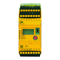
Key:
1: 4-digit display
2: LEDs for PSS operating mode and supply voltage
3: 3-position switch for selecting the standard section’s operating mode
4: Button for scrolling the error stack
5: 2-position switch for selecting the failsafe section’s operating mode
6: Programming device interface
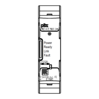
RS 232 (minimum configuration: TxD, RxD, GND)/RS 485
7: User interface
RS 232/RS 485
8: Pushbutton for switching on and off the RS 485 termination on the
user interface
9: Supply voltage connection (24 VDC) for internal supply of the
safety system and the outputs at X1, X2
10: Digital outputs and test pulse outputs
11: Digital inputs
12: Functional earth connection
13: Supply voltage connection (24 VDC) for outputs at X8, X9

 Loading...