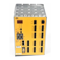
Operating Manual: PSS 3075-3 Series
4-7
Dual-pole outputs (DOZ)
9 dual-pole outputs are available.
The load must be connected between the “+” and “-” terminals. When the
CPU sends a “1” signal via the system bus, the PSS supplies 24 VDC to
the relevant output. The status of the outputs is displayed through LEDs,
which light as soon as a “1” signal (24 VDC) is present at the output.
Internal diagnostic circuitry tests the function of the connected outputs. On
outputs that are switched on, the CPU will alternately switch off the “+” and
“-” terminals as part of each cycle. This is to check that the corresponding
output transistors can be switched off and that there is no interruption to
the load. In addition, outputs that are connected but switched off will be
switched on for approx. 100 µs during each self test. If an error occurs, the
PSS will switch to a STOP condition, switch off the outputs and send a
message to the CPU-display.
All outputs are protected against short-circuit, overload and excess
temperature. They can switch both resistive and inductive loads.

 Loading...