Captain-i - Installation Guide 15
3.1.9 Programming the VU-20N
1. Navigate to “System config 3” menu (#8) and mark ‘+’ under ‘V - Voice’ unit
and under ‘G - Delayed PGM
2. In Zone responses menu (#3), click the desired zone and mark ‘+’ under ‘P -
PGM’, so that the zone will trigger the PGM output (to which the VU-20N
connects) in alarm.
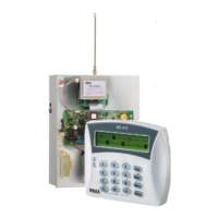
Captain-i
V
(+)
AUDIO
IN
VU-20N
GND
(-)
PGM
Blue
Red
Black
Green
Yellow
Loose
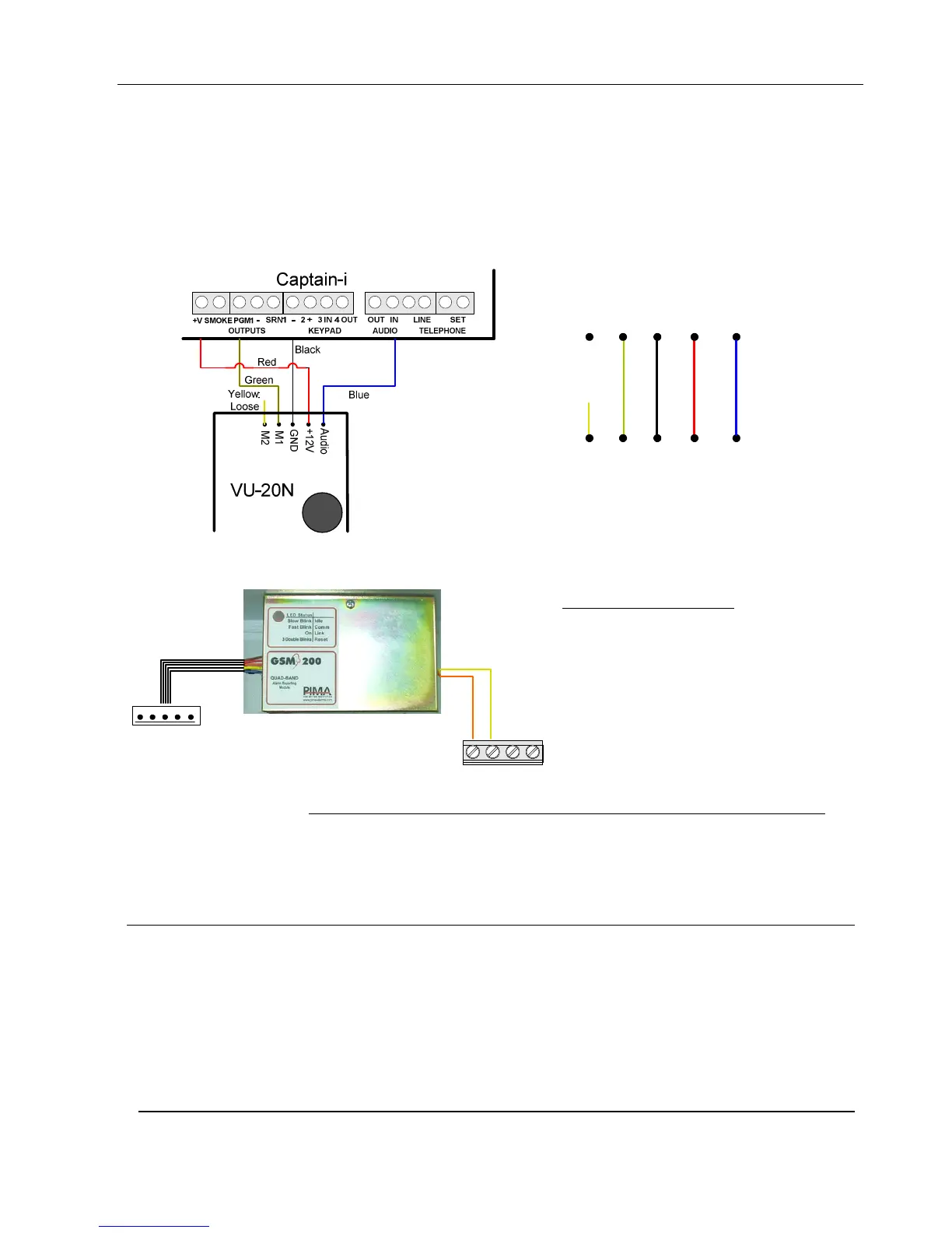
3.1.10 GSM-200 Cellular module
OUT LINE
AUD
IN
Orange
Yellow
TRANSMITTER
Captain-i
To connect GSM-200:
1. Connect the yellow wire to
AUD IN
2. Connect the orange wire to
AUD OUT
3.1.10.1 Connecting VU-20N with GSM-200 Cellular Transmitter
To connect VU-20N together with GSM-200, connect a 5.1 kΩ resistor to one of the
VU-20N blue Audio wires (The second should remain loose).
3.1.11 Mains voltage
Notes:
The cross-section area of the AC main cable must be at least 0.75 mm
2
The hole through which the main cable passes must have either a grommet or
bushing
The wires of the main cable must be tied together with cable tie. The flammability
of the cable tie must be UL 94 V-2 or better
The system should be connected to an automatic circuit breaker that cuts off the
power supply when necessary
 Loading...


