Captain-i - Installation Guide 7
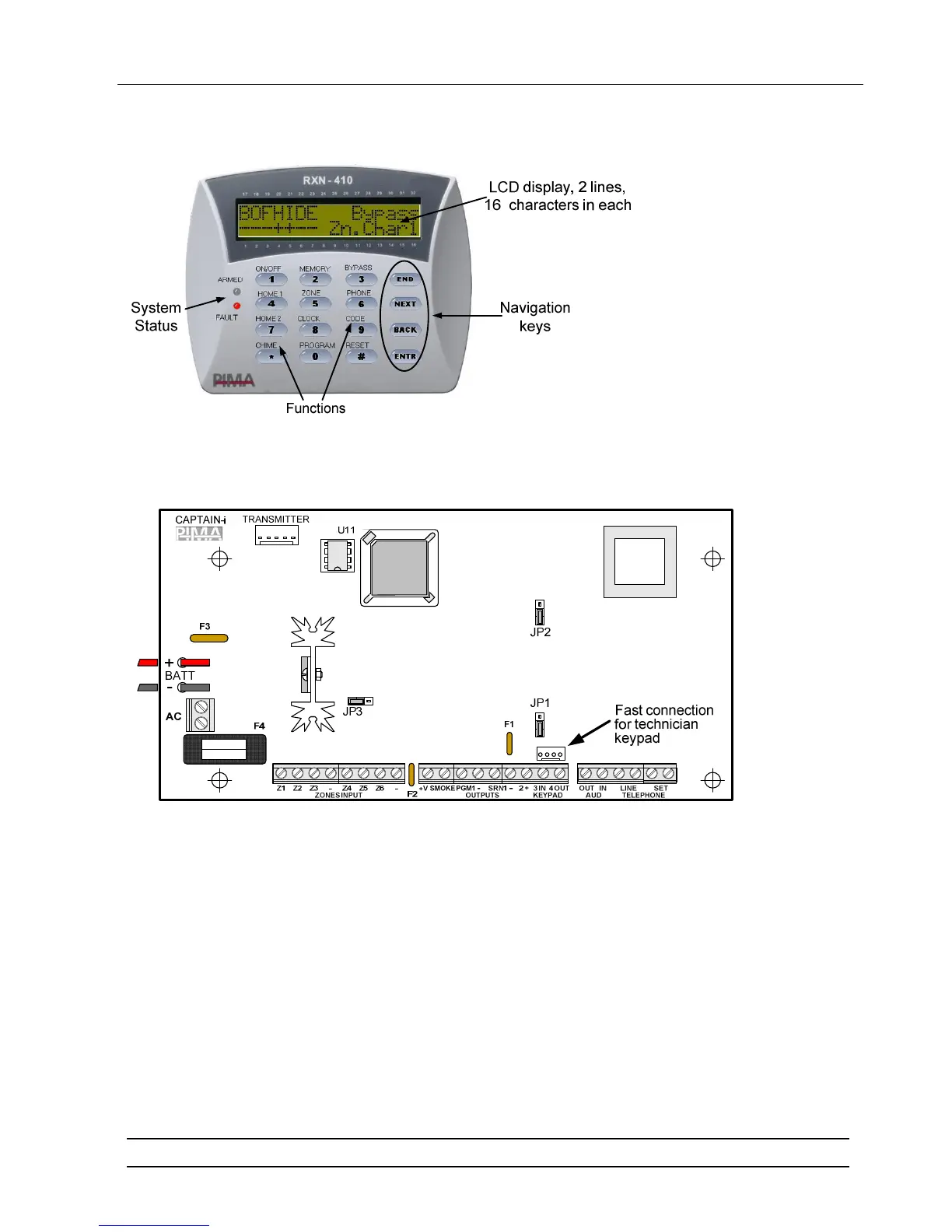
1.4 The LCD Keypad
CAPTAIN-i is fully controlled by the LCD keypad.
1.5 The PCB
CAPTAIN-i PCB
1.5.1 Fuses
♦ F1 - Siren power supply (0.9A)
♦ F2 - Keypad and detectors power supply (750mA). This fuse protects all
the (+V) outputs
♦ F3 - Battery
♦ F4 - Transformer
1.5.2 Connection terminals
♦ AC Voltage Input: 14-16 VAC (+/- 10%) input from the transformer. The cross-
section area of the main AC cable must be at least 0.75mm
2
♦ Connection to Backup Battery: Red wire for the positive (+) contact; Black
wire for the negative (-) contact.
IMPORTANT! Wrong connection of battery contacts can damage the PCB
 Loading...


