10
1
5
STANDBY
ON
STANDBY/ON MENU
DISPLAY
/ SET
– VOL +INPUT
SCREEN SIZE
7 8 9 06
3
4
2
-
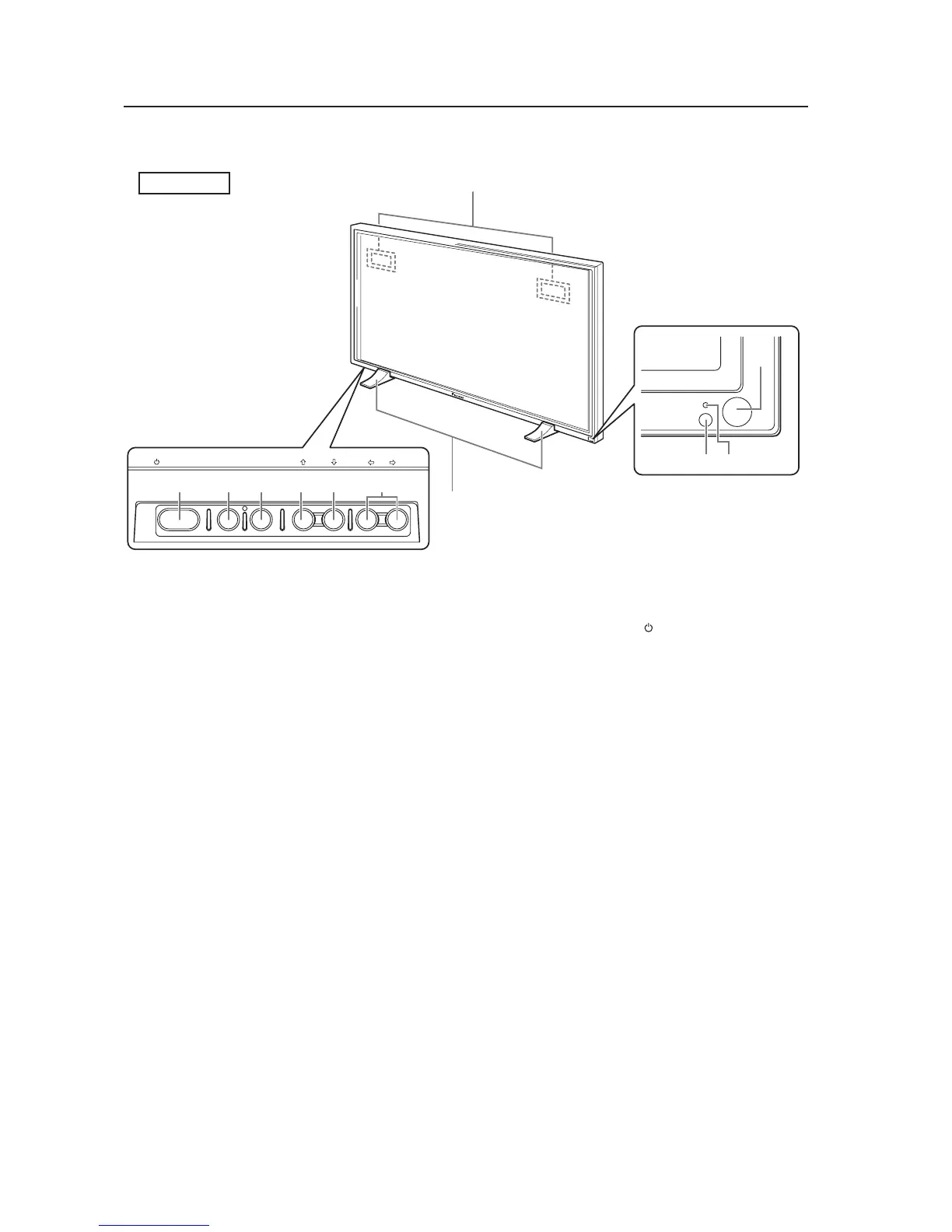
2.3 Controls and Connectors
Controls and Connectors
Main unit
1 Display stand
2 Remote control sensor
Point the remote control toward the remote sensor
to operate the unit.
3 Ambient light sensor
This sensor measures the level of light inside the
viewing room. To take advantage of this sensor, the
[ENGERGY SAVE] option must be set to [AUTO].
4 STANDBY/ON indicator
When the unit is ON the indicator lights green.
When flashing, the indicator denotes an error has
occurred.
The indicator blinks green once every second when
the [POWER MGT.] function is operating.
When the unit is in Standby mode the indicator
lights red.
When flashing, the indicator denotes an error has
occurred.
5 Handles
Operation panel on the main unit
6 STANDBY/ON button ( )
Press to activate the panel or place panel in the
Standby mode.
7 MENU button
Press to reveal and hide the on-screen menu.
8 DISPLAY/SET button
Press to confirm on-screen menu selections and to
change settings.
When not used by on-screen menus, this button
calls the current set status.
9 INPUT (’) button
Except when a menu screen is displayed, this
button changes the input.
0 SCREEN SIZE (‘) button
Except when a menu screen is displayed, this
button changes the screen size.
- VOL +/– (}/]) buttons
When not needed for an on-screen menu, these
buttons are used to adjust the sound volume.
Main unit
Operation panel on the
main unit
Main unit
 Loading...