PDP-6071PU
110
1234
1234
C
D
F
A
B
E
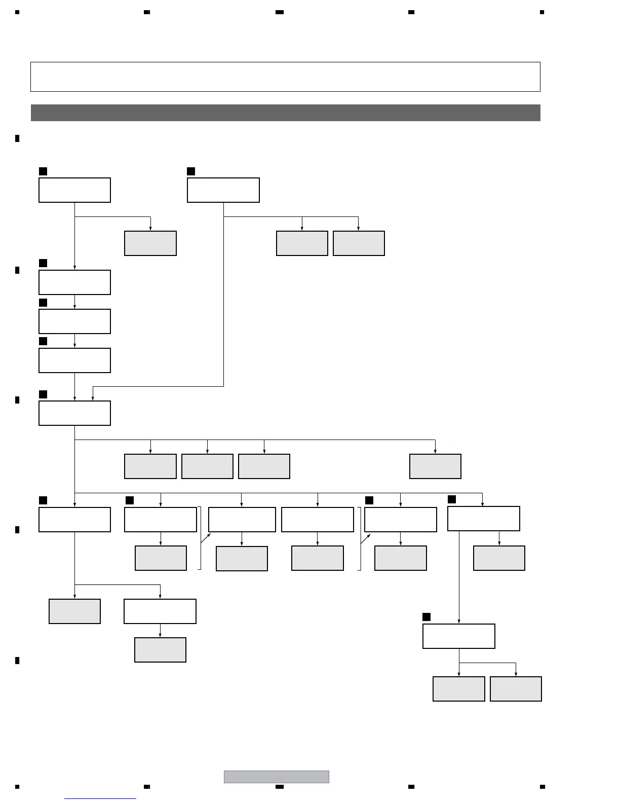
6.2 FLOWCHART OF THE MAIN PARTS AND PC BOARDS EXCHANGE
It is efficient to proceed with removal of the main parts and boards in the order shown in the chart below:
Note: Even if the unit shown in the photos and illustrations in this manual may differ from your product, the procedures
described here are common.
Chart of removal order for the main parts and boards
SIDE KEY
Function button
panel
2
Side input
cover
2
Handle
2
Rear case (607)
2
Under cover (60)
4
Terminal panel A
3
Side input
panel (U)
Function button
shield
Sub frame cover
L, R
2
Side input
shield
PANEL
SENSOR
TANSHI
SIDE
3
POD stay A
MAIN
Tuner stay U
POD
Front chassis
VL Assy 60
SP
TERMINAL
1
5
5
Front case Assy
607
60 DIGITAL
60 Y
DRIVE
AUDIO
60 X
DRIVE
POWER
SUPPLY
607 SCAN A 607 SCAN B
42 &60 LED 60 IR
 Loading...