PDP-6071PU
193
5678
56
7
8
C
D
F
A
B
E
10.5 SPECIFICATION ABOUT THE THERMAL PROTECTION
This model control the FAN drive by pin 149 (FAN ON / OFF)
and pin 17 (Change of FAN control voltage) of MAIN U-com.
When executing [FCNS00], [FCNS01], [FCNS02] command, detect the FAN_NG signal. When NG is detected,
it becomes shutdown. When [FCNS03] command is executed, FAN_NG detection is not operated.
FAN: HIGH
FAN: LO OFF
H
H
H
L
L
–
Assign
Pin 149
(FAN_CONT)
Pin 17
(FAN_CONT_POW)
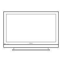
∗ The change of HI / LO have hysterisis curve below.
Reading Value of The Sensor and FAN Drive.
T4
(Outside air 131F)
T2
(Outside air 94F)
T1
(Outside air 82F)
T0
(Outside air 77F)
T3
(Outside air 100F)
FAN: STOP
FAN: LO FAN: HIGH FAN: LO FAN: STOP FAN: LO
FAN: HIGH
SD
Sensor
Temp.
Aims
(Outside Air)
Pin 76 TEMP2 T4 setting 106 268F 131F
T3 setting 142 104F 100F
T2 setting 150 97F 94F
T1 setting 163 86F 82F
T0 setting 170 80F 77F
SD
Low → High
High → Low
STOP → Low
Low → STOP
Set State and FAN Drive
Operation when executing FAN control command
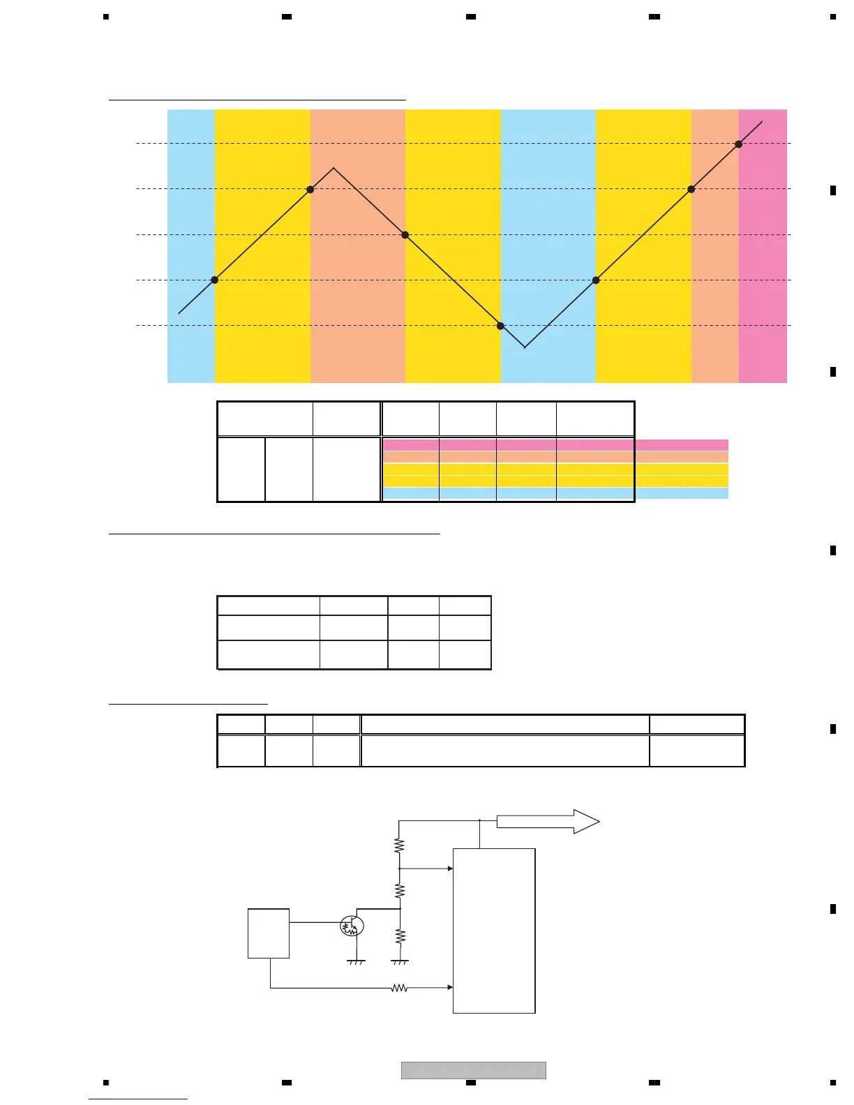
[ Outline Circuit ]
Assign
Power PSW1 State Fan Operation
ON ON ON
According to the reading value of above table sensor.
HIGH or LO
OFF STB FAN_CONT: "L" OFF
Control
REG
FAN_vcc
Vref = 2.64V
H: On
L: Off
Vo
U-COM
17
15
47
33
H: Vo = 11V
L: Vo = 7.6V
149
FAN_CONT
AD Value
8bit
424
566
601
653
679
AD Value
10bit
 Loading...