PDP-6071PU
122
1234
1234
C
D
F
A
B
E
The Definition of Abnormal Cells
Abnormal bright cells: Within five cells on screen.
(fewer than 2 cells within a radius of 1 cm)
Abnormal dark cells: Under fifteen cells on screen.
(fewer than 2 cells within a radius of 1 cm)
Count abnormal cells at a distance of 1 m from panel.
If abnormal cells won't occur longer than one second, do not count the
abnormal cells.
Do not count still dark cells and bright cells.
Vsus setting = 207 [V]
Vsus margin = 17 [V] or more
Vofs setting = 24 to 49 [V]
Vofs margin = 19 [V] or more
Vyprst setting = 250 to 300 [V]
Standard settings of the unit at shipment:
Vsus = 207 [136] [V]
Vofs = 15 [024] to 60 [255] [V]
Vyprst = 240 [000] to 302 [158] [V]
Vxnrst = 180 [V]
Vh = 130 [V]
Vadr = 60 [V]
(Ranges of the adjustable voltage
when the upper and lower limits of
each voltage are to be checked in
this flowchart)
Ranges of the adjustable voltages
When calculating the voltage, round off the fractional part.
(For circuit protection, it is desirable to set the voltage to a lower value.)
Switch modes to start the voltage adjustment, as follows:
Enter Factory mode.
Display RST MASK 01 (white).
Mode switching
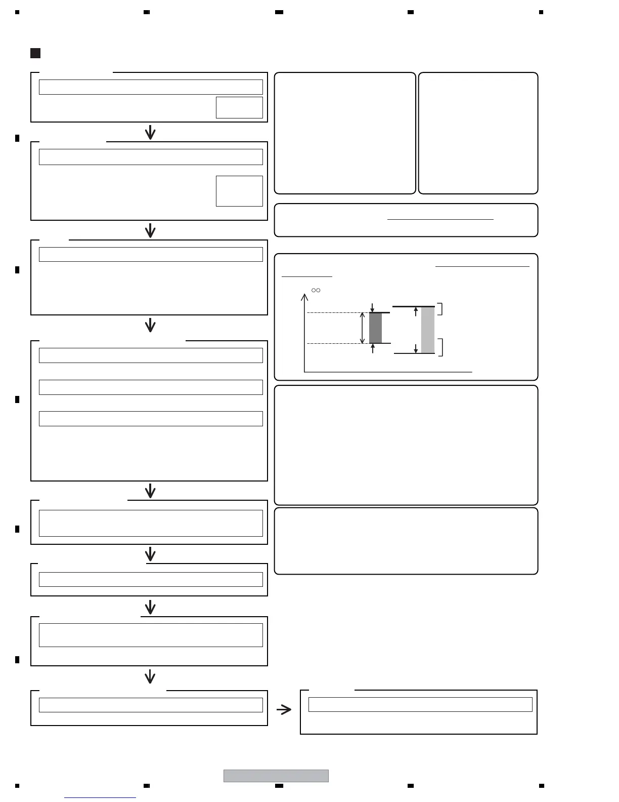
For margin measuring, be sure to read the value within the hysteresis
(stricter value).
Note: The voltages in the flowcharts are given in absolute values
(without ±).
With erroneous discharge
With erroneous discharge
Upper limit of the voltage
Lower limit of the voltage
Read the voltage
within this range.
Without erroneous
discharge
Down
V
Down
Up
Up
OUTLINE
FAY
MKS S51
Set Vsus and Vyprst, and tentatively set Vofs:
VOL SUS : Set to 136 (207[V]).
VOL RST P : Set to the voltage indicated
on the panel label.
VOL OFFSET : Tentatively set to the voltage
indicated on the panel label.
Voltage setting
VSU136
VRP∗∗∗
VOF∗∗∗
With the black mask displayed, check if there are stationary
or horizontally moving lit cells.
CA check with black
Perform aging with the fully white screen for 10 minutes
Measuring the lower limit of Vofs
Vofs setting
To prevent an error caused by the temperature characteristics
and to let the unit show its full properties after letting it sit,
perform aging for 10 minutes to raise the panel temperature to
a certain extent. This ensures the accuracy of inspection and
adjustment.
Aging
Check that each voltage value is correctly set.
Signals to be measured: Pale purple, Sky color, Yellow egg color
Measuring the upper limit of Vofs
Signals to be measured: red 1023+, green 1023+, and blue 1023+
In a case where the margin of Vofs is between 19 and 22 [V]:
Vofs set voltage = Vofs_max - 8 [V]
In a case where the margin of Vofs is 23 [V] or more:
Vofs set voltage = Vofs_max - 12 [V]
Confirmation of settings
After the voltage adjustment is finished, make the following
settings:
Command transfer
Check that the each voltage is properly set.
Mask: OFF, Factory: OUT
Confirmation of setting data
Check that the picture is properly displayed.
Use DVD, LD, and broadcast signals for checking.
CA check
Actual Vofs adjustment (2 to 6)
Vsus = 207 [136] [V]
Vofs = 24 [071] to 49 [199] [V]
Vyprst = 250 [026] to 310 [179]
[V]
Vxnrst = 180 [V]
Vh = 130 [V]
Vadr = 60 [V]
(Ranges of voltage settings
for this unit)
Ranges of the voltage
settings
 Loading...