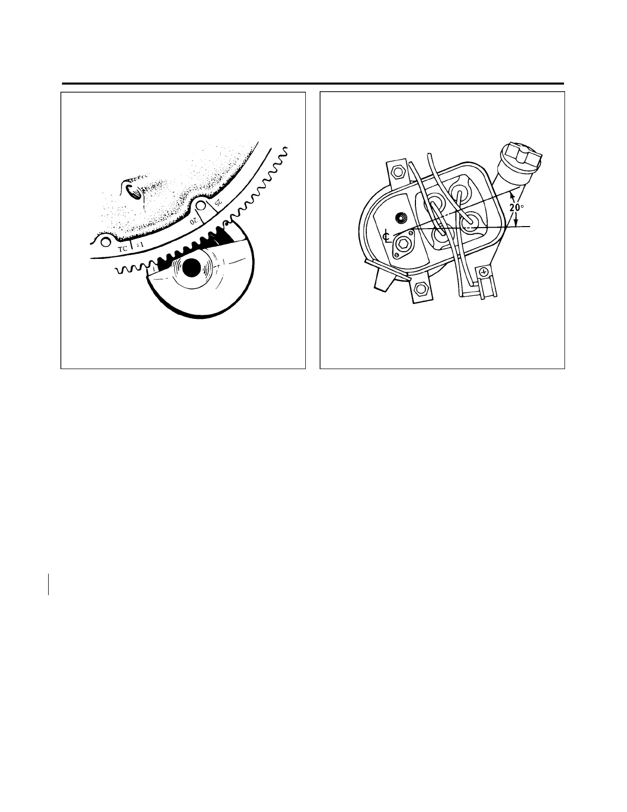
Figure 74-28. Engine Timing Marks Figure 74-29. Magneto Adjustment Limits
INSTALLATION AND TIMING PROCEDURE. (Timing Magneto To Engine)
Although only the left magneto is equipped with an impulse coupling, the timing procedure, in the
following paragraphs, is the same for both magnetos.
1. Remove the spark plug from No. 1 cylinder and place a thumb over the spark plug hole. Rotate the
crankshaft in direction of normal rotation until the compression stroke is reached, this is indicated by a positive
pressure inside the cylinder tending to push the thumb off the spark plug hole. Continue rotating the crankshaft
in direction of normal rotation until the advance timing mark (20) on the front face of the starter ring gear is in
exact alignment with the small hole located at the two o’clock position on the front face of the starter housing.
(Refer to Figure 74-28.)
—NOTE—
The advance timing mark on the top face of the starter ring gear
is marked at both 20° and 25° BTC. Use only the 20° BTC mark
when timing the magnetos to the engine.
—NOTE—
If the crankshaft is accidentally turned in the direction opposite
normal rotation, repeat the above procedure as accumulated
backlash will make the final timing incorrect.
Effectivity 74-11-04
PA-28RT-201 Page 74-28
Revised: February 23, 1979
3E13
PIPER AIRCRAFT
PA-28RT-201 / 201T
MAINTENANCE MANUAL
 Loading...


