SWITCHING.
REMOVAL OF IGNITION SWITCH.
1. Insure the ignition switch is in the OFF position.
2. Gain access to and disconnect the power lead (+) from the battery.
3. Remove the ignition switch retaining nut from the switch on the forward side of the instrument panel
and withdraw the switch from the panel.
4. Mark the wires, and note their position on the switch, then disconnect the wires.
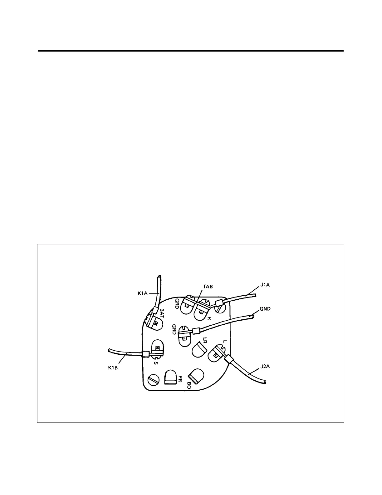
INSTALLATION OF IGNITION SWITCH. (Refer to Figure 74-45.)
1. Attach wires to switch as shown in Figure 74-45.
2. Check for proper operation of the ignition switch as follows:
A. Remove the P-lead from the right magneto.
B. Attach the P-lead of the right magneto to an ohmmeter and to the airframe ground.
C. With the switch in the “OFF”, “L” or “START” positions the ohmmeter should indicate a closed
circuit.
D. With the switch in the “R” or “BOTH” positions the ohmmeter should indicate an open circuit.
3. Reconnect the P-lead to the magneto.
4. Position the ignition switch in the instrument panel and secure with retaining nut.
5. Connect the power lead (+) to the battery and reinstall any access covers previously removed.
Figure 74-45. Ignition Switch Wire Positions
74-30-02
Page 74-40
Added: July 24, 1981
3F1
PIPER AIRCRAFT
PA-28RT-201 / 201T
MAINTENANCE MANUAL
 Loading...


