A95I
242 243
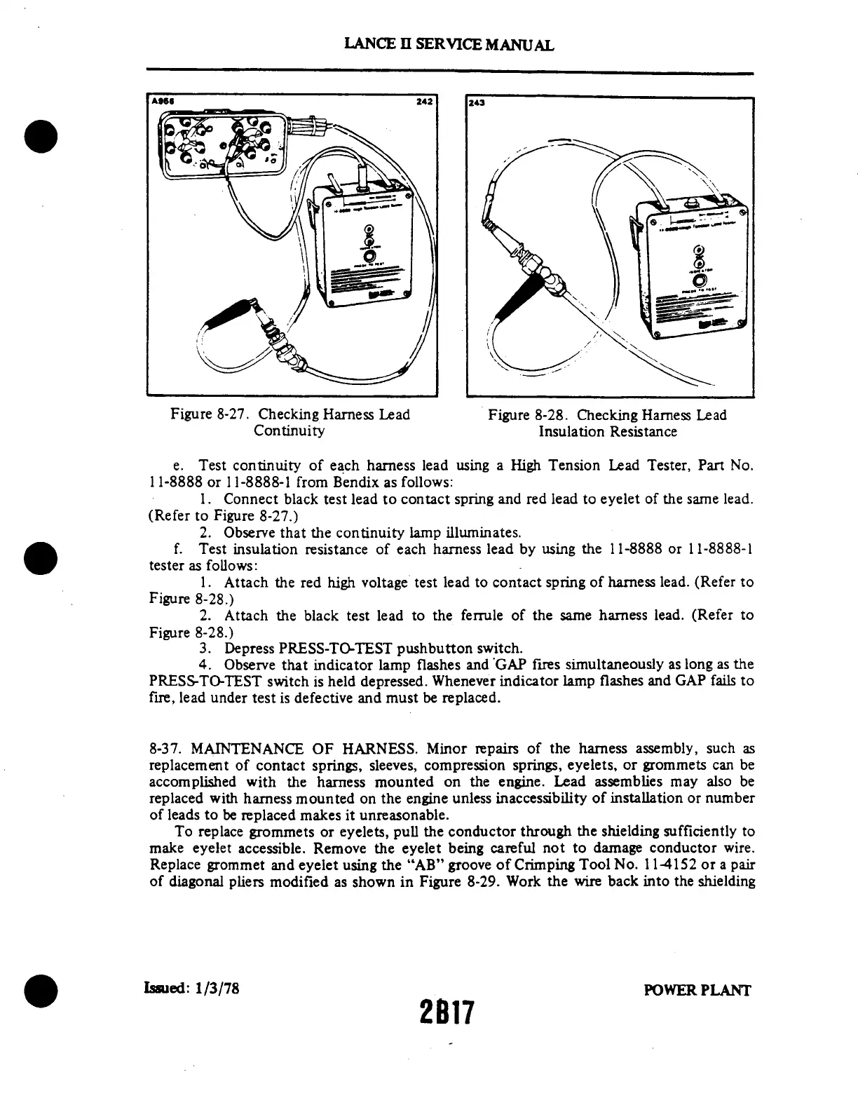
Figure 8-27.
Checking Harness
Lead
Figure 8-28.
Checking Harness
Lead
Continuity
Insulation Resistance
e. Test continuity of each
harness lead using a High Tension
Lead Tester, Part No.
11-8888 or 11-8888-1 from Bendix as follows:
1. Connect black test lead
to contact spring and red lead to
eyelet of the same lead.
(Refer to Figure 8-27.)
2. Observe that the continuity lamp illuminates.
f. Test insulation resistance of each harness lead by using the 11-8888 or 11-8888-1
tester as follows:
1. Attach the red
high voltage test lead to contact
spring of harness lead. (Refer to
Figure 8-28.)
2.
Attach the black test lead to the
ferrule of the same harness lead.
(Refer to
Figure 8-28.)
3. Depress PRESS-TO-TEST pushbutton switch.
4. Observe that indicator
lamp flashes and 'GAP fires
simultaneously as long as the
PRESS-TO-TEST switch is held depressed. Whenever indicator lamp flashes and GAP fails to
fire, lead under test is defective and must be replaced.
8-37. MAINTENANCE OF HARNESS. Minor repairs of the harness assembly, such as
replacement of contact springs,
sleeves, compression springs, eyelets,
or grommets can be
accomplished
with the harness mounted on the
engine. Lead assemblies may also
be
replaced with harness mounted on
the engine unless inaccessibility of installation
or number
of leads to be replaced makes it unreasonable.
To replace grommets
or eyelets, pull the conductor through
the shielding sufficiently to
make eyelet accessible. Remove the eyelet being careful not to damage conductor wire.
Replace grommet and eyelet using the "AB" groove of Crimping Tool No. 11-4152 or a pair
of diagonal pliers modified as shown in Figure 8-29. Work the wire back into the shielding
Issued:
1/3/78
POWER
PLANT
2B17
LANCE
II SERVICE
MANUAL
 Loading...

