Step 8
Set up myRIO and run LabVIEW code
8.1. Follow the hardware and software setup instructions in
the “Set Up Your Control System” section. Make sure you:
• Connect the motor board to MXP B and connect
the sensors and actuators to the motor board
• Connect the system to power
• Install software to your PC (via disk or web installer)
and myRIO (via the Getting Started Wizard)
• Configure myRIO for WiFi
8.2. Connect to the myRIO WiFi signal (remember the SSID
you chose) using the network icon on the bottom right corner of your screen, similar to how you connect to any
other WiFi network
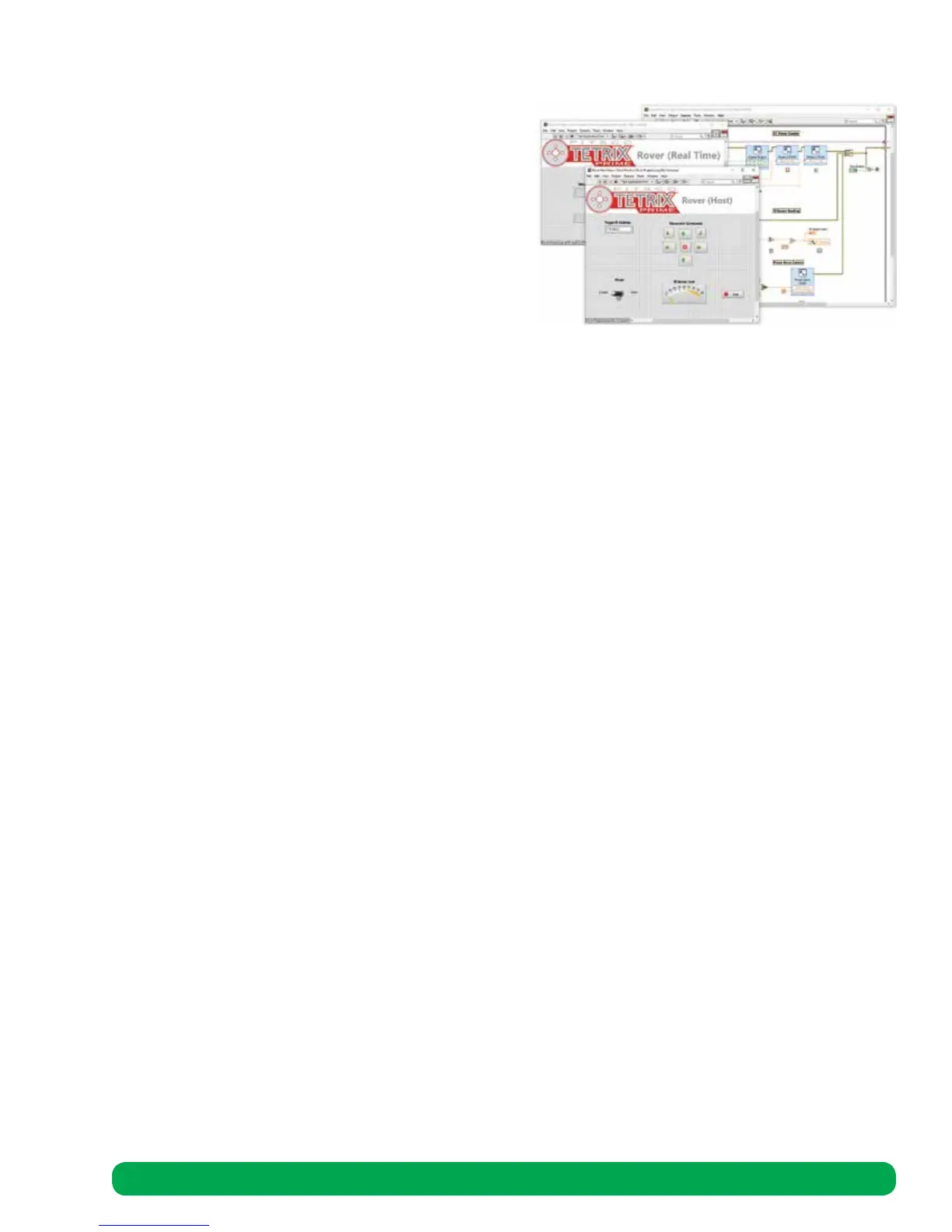
8.3. Navigate to Rover code using the following path: C:\Users\...\Desktop\National Instruments\Pitsco Tetrix Prime for NI
myRIO\Rover Vehicle and open “Rover Project”
8.4. Make sure the IP Address in the parenthesis next to the “NI-myRIO” line item matches the myRIO wireless adapter
IPv4 address in the Network Adapters window of the myRIO Configuration menu. If it doesn’t: Right click the NI
myRIO line item, and select “Properties” Update the IP address and click OK
8.5. Right click the NI myRIO line item and select “Connect.”
8.6. Open “Rover RT Main.vi” by double clicking the line item in the project and press the run arrow in the upper left
corner or press ctrl + r to run
8.7. Open “Rover Host Main.vi” under My Computer
8.8. Make sure that the IP address on the Front Panel matches the myRIO wireless IP Address
8.9. Press the run arrow in the upper left corner or press ctrl + r to run
8.10. Use the buttons to move the rover and the switch to open and close the pincer. View the meter to detect objects
near the rover
Step 9: Troubleshooting
9.1. If you are having trouble sending messages from your host computer to myRIO, make sure that the IP address on the
Front Panel of the Host VI matches the myRIO wireless IP address
9.2. If the rover drives in the wrong direction, make sure that the motors are connected as described in step 7.1.
Next Steps
• Learn about how the Rover Vehicle relates to control theory in the next section
• Get some ideas for expanding the Rover on the first page of this section
Rover Vehicle Assembly 79
 Loading...