10 - ATR142 - User manual
10 11 12
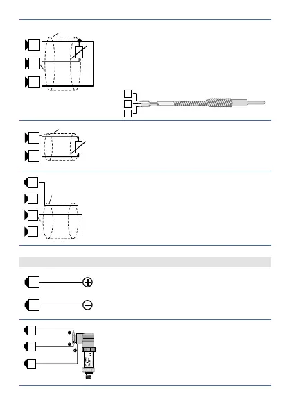
PT/NI100
Shield/Schermo
For thermoresistances PT100, NI100
• For the three-wire connection use
wires with the same section
• For the two-wire connection short-
circuit terminals 10 and 12
• When shielded cable is used, it should
be grounded at one side only
Shield/Schermo
PTC/NTC
10 11
For thermoresistances NTC, PTC,
PT500, PT1000 e potentiometers
• When shielded cable is used, it should
be grounded at one side only to avoid
ground loop currents
Shield/Schermo
+VDC
9
10 11 12
V/I
+-
For linear signals V/mA
• Comply with polarity
• When shielded cable is used, it should
be grounded at one side only
5.1.c Examples of Connection for linear input
0...10V
1112
For signals 0..10V
• Comply with polarity
PRESSURE TRANSMITTER
SENSORE DI PRESSIONE
0/4...20mA
A
B
C
1112 9
For signals 0/4..20mA with three-wire
sensor
• Comply with polarity
C = Sensor output
B = Sensor ground
A = Sensor power supply (12V/30mA)