54 - ATR142 - User manual
O
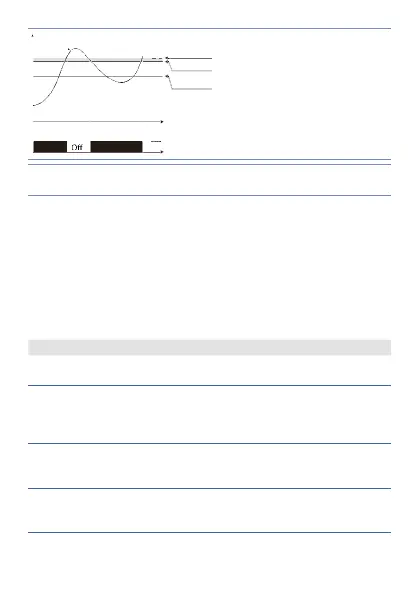
On On
Hysteresis
parameter
> 0
Pv.
Alarm Spv
Command Spv
Time
Alarm output
Lower deviation alarm
value of alarm setpoint
less than “0” and
hysteresis value greater
than “0” (Parameter 28
a .1 . H y .
> 0). **
* The example refers to alarm 1; the function can also be enabled for
alarm 2 on model that include it.
** a) The example refers to alarm 1; the function can also be enabled for
alarm 2 on model that include it. b) With hysteresis less than “0” (
a .1 . H y .
< 0) the segmented line moves above the alarm setpoint.
14 Table of Anomaly Signals
If installation malfunctions, controller will switch off
regulation output and will report the anomaly. For example,
controller will report failure of a connected thermocouple
visualizing
e -05
fl ashing on display for other signals, see table
below.
Cause What to do
E - 01
sYs . e.
Error in E²PROM cell
programming
Call Assistance
E-02
sYs . e.
Cold junction
sensor fault or room
temperature outside of
allowed limits.
Call Assistance
E-04
sYs . e.
Incorrect confi guration
data. Possible loss of
calibration values.
Check if the confi gu-
ration parameters are
correct.
E-05
prb .
Thermocouple open or
temperature outside of
limits.
Check the connection
with the sensors and
their integrity.