14 - ATR142 - User manual
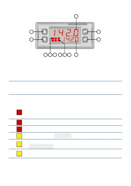
7 Display and keys functions
5
4
3
8
7
6
2
1
M T R
2 3
9
10
12
11
ATR 142
1
7.1 Numeric indicators (Display)
1
1234
Normally displays the process. During the
confi guration phase, it displays the parameter
being inserted.
2
1234
Normally displays the setpoint. During the
confi guration phase, it displays the parameter
value being inserted.
7.2 Meaning of status lights (Led)
3
1
ON when the output command is on. For
motorised valve command, led is ON when valve
is opening and blinks when closing.
4
2
ON when alarm 1 is on.
5
3
ON when alarm 2 is on.
6
M
ON when the “Manual” function is on.
7
T
ON when the controller is running an
“Autotuning” cycle.
8
R
ON when the controller communicates via serial
port.