User manual - ATR142- 9
5 Electrical wirings
Although this controller was designed to resist electro-
magnetic interferences in industrial environments, please
observe following safety guidelines:
• Separate the control line from the power wires.
• Avoid proximity of remote control switches, electroma-
gnetic contactors, powerful engines and in all instances
use specific filters.
• Avoid proximity of power groups, especially those with
phase control
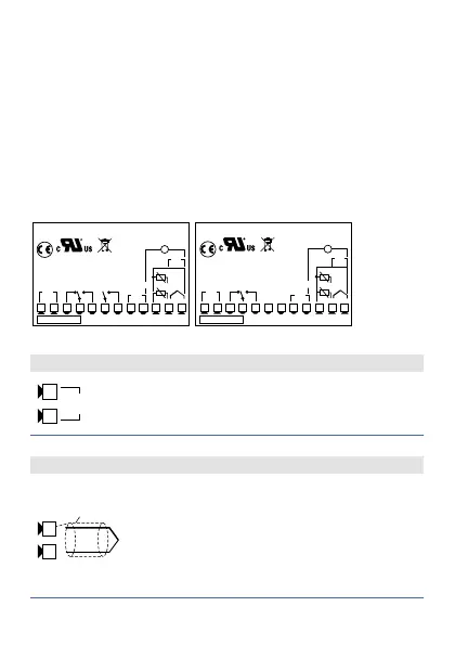
5.1 Wiring diagram
PIXSYS
10A 230V
Cosf 1
3A 230V
Cosf 0.8
Q1
PTC/NTC
-
+
Tc
+VDC
SSR
1 2 3 4
5
6 7 8 9
10 11 12
-
+
I
V/I
+
-
PT/NI100/1K
2 wire 4/20mA
Power
5A 230V
Cosf 1
1A 230V
Cosf 0.8
Q2
Memory
1
ATRxxx-xx
-
+
SUPPLY
PIXSYS
10A 23a0V
Cosf 1
3A 230V
Cosf 0.8
Q1
PTC/NTC
-
+
Tc
+VDC
SSR
1 2 3 4
5
6 7 8 9
10 11 12
-
+
I
V/I
+
-
PT/NI100/1K
2 wire 4/20mA
Power
Memory
1
-
+
ATRxxx-xxT
-
+
RS485
SUPPLY
ATR142-ABC ATR142-ABC-T
5.1.a Power Supply
1 2
24...230V
AC/DC
Switching power supply with extended
range 24..230 Vac/dc ±15% 50/60Hz –
5,5VA.
5.1.b AN1 Analogue Input
-
+
Tc
11 12
Shield/Schermo
For thermocouples K, S, R, J.
• Comply with polarity
• For possible extensions, use
compensated cable and terminals
suitable for the thermocouples
used(compensated)
• When shielded cable is used, it should
be grounded at one side only