EasyManua.ls Logo

Pixsys ATR142 - 5 Electrical Wirings; Wiring Diagram

Pixsys ATR142
52 pages
Print Icon
To Next Page IconTo Next Page
To Previous Page IconTo Previous Page
Loading...
6
5
Electrical wirings
Although this controller was designed to resist noises in
industrial environments, pease notice following safety
guidelines:
Separate the feeder line from the power lines.
Avoid placing near units with remote control switches,
electromagnetic contactors, high powered motors and in all instances
use specific filters.
Avoid placing near power units, particularly if phase controlled.
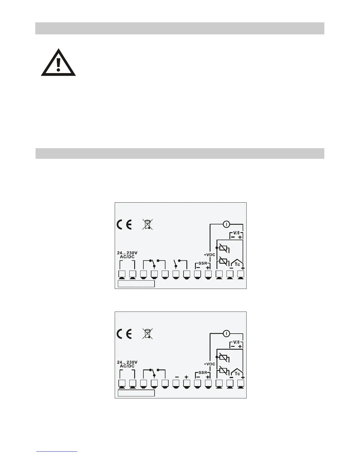
5.1 Wiring diagram
The connections are reported below for the three models available.
PIXSYS
ATR142-ABC
1 2 3 4 5
6
7
8
9
10
11
12
PT/NI100/1K
2 wire 4/20mA
Power
Memory1
5A 230V
Resistive
1/8HP
Q2
8A 230V
Resistive
1/2HP
Q1
1 2 3 4 5
6
7
8
9
10
11
12
PT/NI100/1K
2 wire 4/20mA
Power
Memory1
RS485
PIXSYS
ATR142-ABC-T
8A 230V
Resistive
1/2HP
Q1

Related product manuals