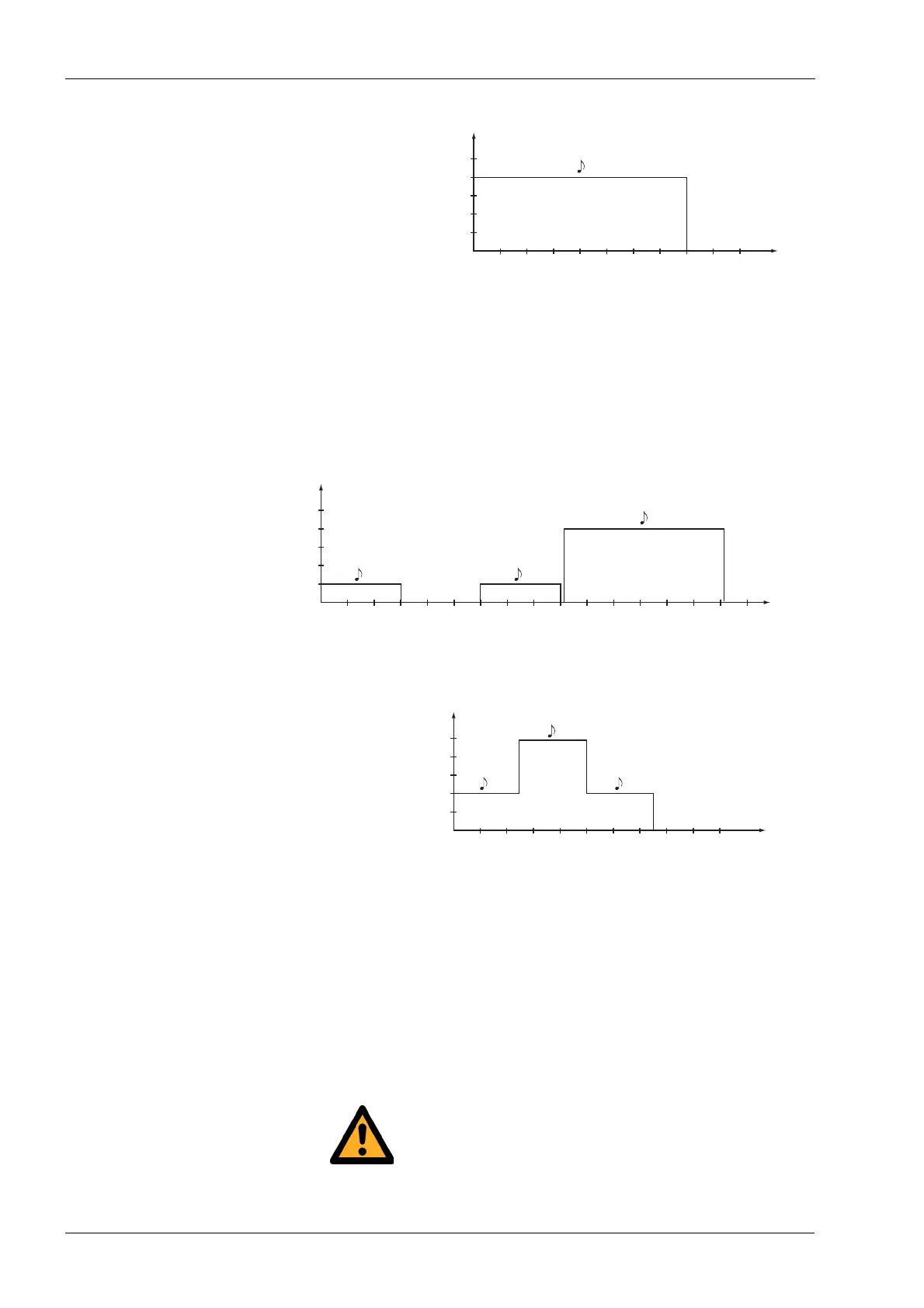
11 CHAIR SIGNAL TONES
26 Planmeca Chair User’s manual
1. A stop microswitch is activated, that is, the backrest,
the stop plate stop bar or stop cover is lifted.
2. The lift/backrest motor position sensor is loose when
you are trying to drive the seat/backrest.
3. The lift/backrest motor does not operate as desired.
The reason can be either a damaged motor or a fault
in the PCB.
The chair is in the programming mode.
The calibration mode is entered.
The calibration is described in the
Planmeca Chair
technical manual
.
In the calibration mode of the chair, both the lift and
backrest motors can be driven regardless of the voltage
signal from their position sensors. Therefore, this mode is
convenient for testing whether the cause for a non-
operational motor is the motor itself, the processor PCB or
the position sensor and/or its cable. If the motor can be
run in the calibration mode, the fault site refers to the
sensor and/or its cable.
In the calibration mode the motors can be driven to
their mechanical limits.
100 200 300 400 500 600 700 800 900 1000 t/ms
Hz
800ms
660
739.5
832.5
1100
1479
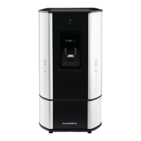
100 200 300 400 500 600 700 800 900 1000 1100 1200 1300 1400 1500 1600 t/ms
Hz
300ms 300ms
600ms
660
739.5
832.5
1047.5
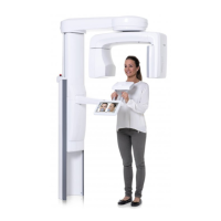
100 200 300 400 500 600 700 800 900 1000
t/ms
Hz
250ms 250ms
250ms
660
739.5
832.5
1100
1479



 To Next Page