SQF-3-37
Replacement
Adjustment
29 November 2006
PCB
Removal
1. Remove Rear Cover (
3.1.2).
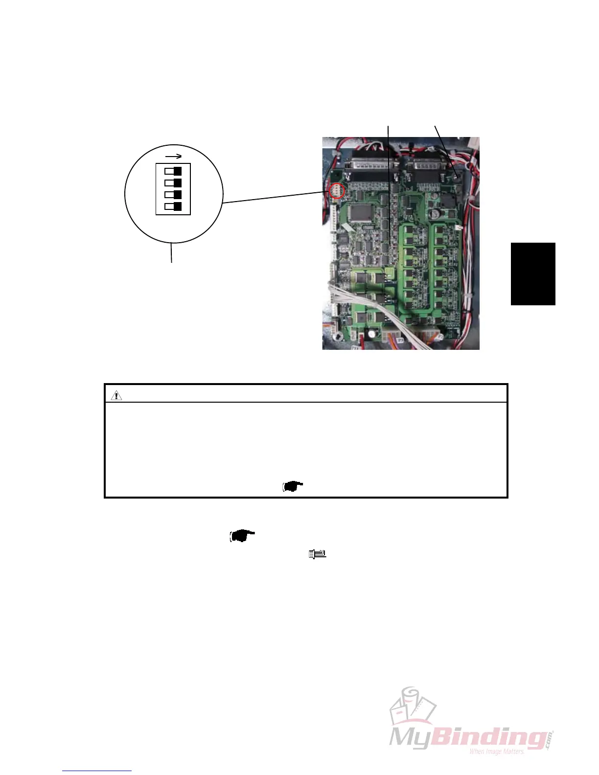
2. Remove all connectors from PCB [A] (
x 8).
3. Remove PCB by squeezing barbs [B] on the standoffs ( x4) securing PCB.
REPLACEMENT
1.
Reverse the removal procedure.
NOTE:
Make sure all DIP switches are in off position [C].
NOTE:
Make sure correct software version is loaded in the PCB.
3.6 PCB
3.6.1 PCB MD6DC “D”
ON
[C]
[A]
[B]
CAUTION
ESD Hazard! ESD (Electrostatic Discharge) can cause software crashes,
data and/or communications problems. Failure to use proper ESD pro-
cedures will cause damage to electronic components (example: PCBs).
ESD problems can be minimized by maintaining all machine ground con-
nections, ensuring the proper handling of circuit boards and sensors. Use
ESD protection when working near PCBs. Failure to use ESD protection is
likely to result in a PCB failure ( Service Manual BM 200 3.1 ).