15
HEATED HOSE INSTALLATION
CAUTION! The material delivery Heated Hoses are color coded Red
and Blue allowing the user to recognize them. The Red corresponds
to the Isocyanate (Iso, A) and the Blue to the Polyol (Poly, R). To avoid
connection errors the Coupling Connections of the Iso (A) and Poly
(R) Heated Hoses are also different sizes, which makes it difficult to
swap connections.
NOTE! The material delivery Heated Hoses are capped at the ends to
prevent absorbing moisture. Do not remove caps until the Heated Hoses
are going to be installed on the Proportioner.
1. Lay out all the Heated Hose assemblies end to end aligning the Iso “A” (red) and Poly
“R” (blue) and connect the respective Coupling Connections using the appropriate sized
open-end wrench after ensuring Heated Hose assemblies lay flat.
CAUTION! Take care to not cross-thread or over-tighten the Coupling
Connections. Thread seal tape or compound is not required for this
tapered seat Coupling Connections.
2. Connect the material Heated Hoses to the outlets of the respective Heaters i.e. Iso (A)
Heated Hose to the Iso (A) Heater and the Poly (R) Heated Hose to the Poly (R) Heater
ensuring Heated Hose assemblies lay flat.
a. For half inch hose assemblies, all required fittings and instructions are included in
kit 200212
3. Connect Air Hose Coupling Connections.
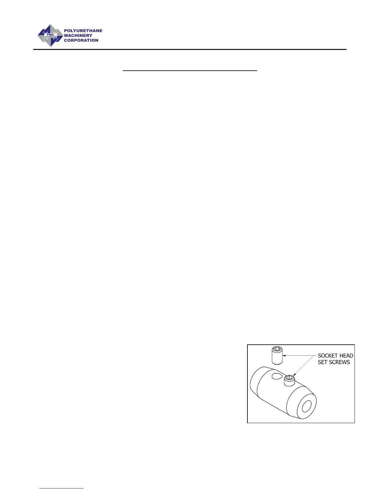
4. Connect the Heated Hose power wires to the “Fast-Lock” Connector (Part # KT-00029A)
coming from the Hose Heat Transformer as follows:
a. Loosen the Socket Head Set Screw to allow
insertion of the Heated Hose electrical wire
Terminal.
b. Insert the Terminal into the “Fast-Lock”
Connector Body.
c. Securely tighten the Socket Head Set Screw.
d. Install electrical tape around Connector Body.
NOTE! A good practice is to add some dielectric grease (Permatex 67VR
or equivalent) to the outside of the Terminal prior to insertion.