Point Grey Research Grasshopper Technical Reference
Camera Physical Properties
Revised 26-Nov-10
Copyright (c) 2010 Point Grey Research Inc.
14
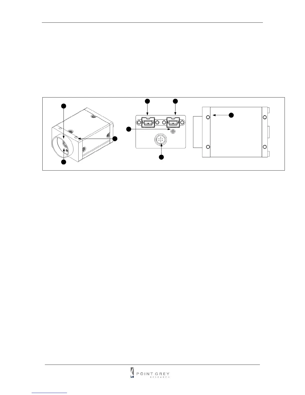
2 Camera Physical Properties
2.1. Physical Description
1. Lens holder (C-
mount)
Attach any C-mount
lens or other optical
equipment. Consult
the section Lens
Setup and
Compatibility for full
details.
2. Glass / IR filter
system
Refer to the Dust
Protection and the
Infrared Cut-Off
Filters section for
more information.
3. M3x0.5 mounting
holes
Refer to the
Mounting section for
full details.
4. General Purpose I/O connector
The 8-pin GPIO connector is used for external triggering,
strobe output or digital I/O. Refer to the General Purpose
Input/Output section for more information.
5. Status LED
This light indicates the current state of the Grasshopper
operation. Refer to the section Status Indicator LED.
6. IEEE-1394b connector
7. IEEE-1394b connector
The camera uses standard 9-pin 1394b connectors. M3
screw holes are located on either side of the connectors
for secure connections to the 9-pin locking 1394b cable.
See the IEEE-1394 Connector section for full connector
details.
8. M3x0.5 mounting holes
Refer to the Mounting section for full details.
3
1
2
3
4
5
6
7
8