Point Grey Research Grasshopper Technical Reference
Camera Interface
Revised 26-Nov-10
Copyright (c) 2010 Point Grey Research Inc.
18
3 Camera Interface
3.1. IEEE-1394b Connector
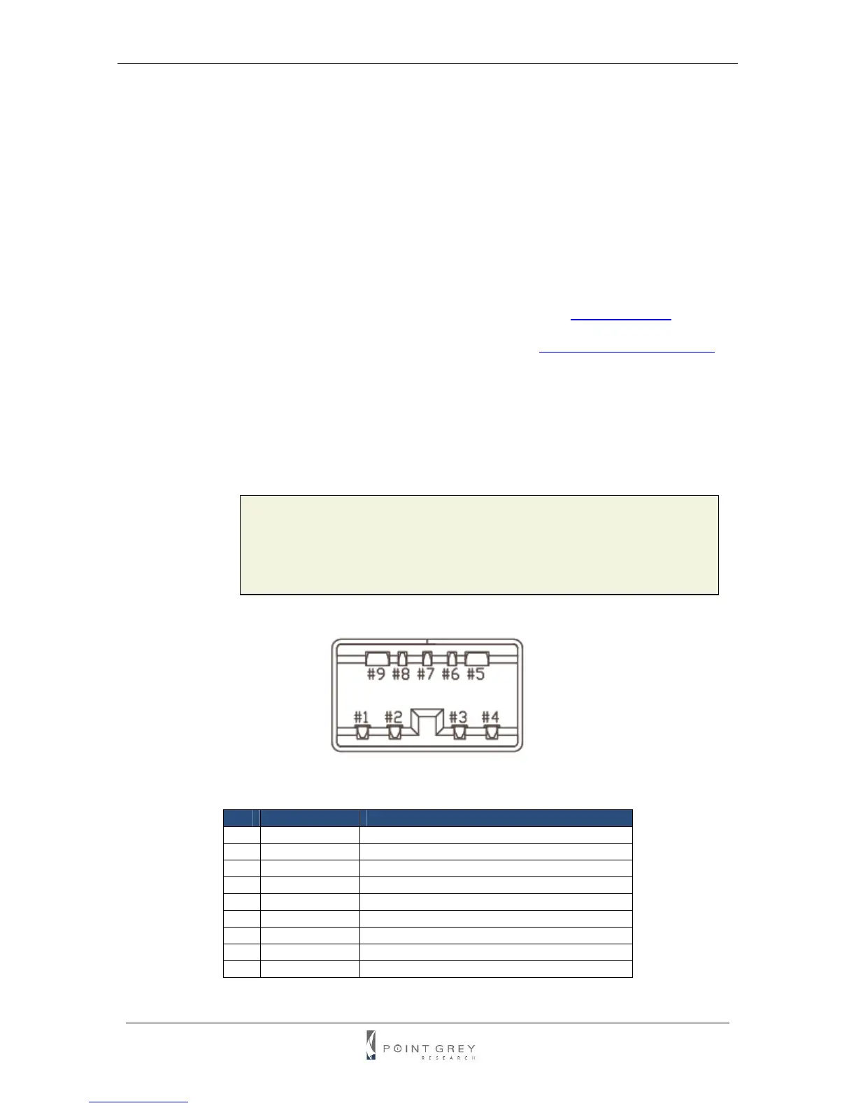
The camera has 2 standard 9-pin IEEE-1394b connectors (pin configuration shown below) that is
used for data transmission, camera control and powering the camera. For more detailed
information, consult the IEEE-1394b Standard document available from
www.1394ta.org.
For a full description of the features and benefits of 1394b, refer to
Knowledge Base Article 206.
3.1.1. Daisy Chaining
As the camera has 2 IEEE-1394b connectors, it is possible to connect multiple cameras (and/or
hubs) in a daisy-chained manner. This allows multiple cameras to be easily connected to a single
host controller. However, the maximum bandwidth available for all cameras is still restricted to
800Mbps (for IEEE-1394b) or 400Mbps (for IEEE-1394a).
L
While the Grasshopper is an IEEE-1394b device, it is backward
compatible with the IEEE-1394a 400Mb/s standard, and can therefore
be connected to any 1394a OHCI host adapter using a 9- to 6-pin
cable (included with Grasshopper Development Kits).
Figure 2: IEEE-1394b connector pin configuration
Pin Signal Name Comment
1 TPB- Twisted Pair B (Minus)
2 TPB+ Twisted Pair B (Plus)
3 TPA- Twisted Pair A (Minus)
4 TPA+ Twisted Pair A (Plus)
5 TPA (R) Twisted Pair A (Reference Ground)
6 V
G
Power (Ground)
7 SC Status Contact (Reserved for Future Use)
8 V
P
Power (Voltage)
9 TPB (R) Twisted Pair B (Reference Ground)