Point Grey Research Grasshopper Technical Reference
Camera Operations and Features
Revised 26-Nov-10
Copyright (c) 2010 Point Grey Research Inc.
42
1. Retransmission of an image is required due to data loss or corruption.
2. Multiple camera systems where there is insufficient bandwidth to capture images in the
desired configuration.
This feature is controlled using the Frame Buffer register located at 0x12E8. For more
information, please see TAN2007004: Accessing the On-Camera Frame Buffer.
4.5.12. High Dynamic Range (HDR) Mode
The Grasshopper can be set into a High Dynamic Range mode in which the camera will rotate
between 4 user-defined shutter and gain settings. This allows images representing a wide range
of shutter and gain settings to be collected in a short time to be combined into a final HDR image
later. The Grasshopper does not create the final HDR image; this must be done by the user.
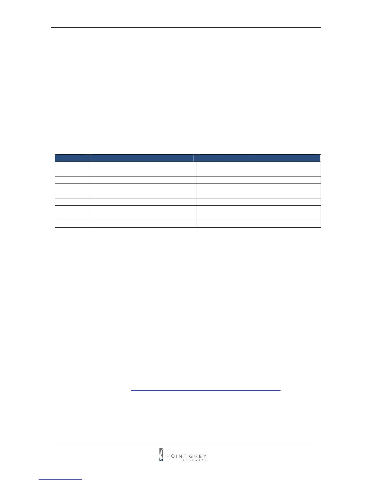
The format of the HDR registers is as follows:
Offset Register Remarks
0x1800 HDR control register Toggle bit [6] to enable/disable HDR
0x1820 HDR shutter register for image 0 Similar to SHUTTER register 0x81C
0x1824 HDR gain register for image 0 Similar to GAIN register 0x820
0x1840 HDR shutter register for image 1 Similar to SHUTTER register 0x81C
0x1844 HDR gain register for image 1 Similar to GAIN register 0x820
0x1860 HDR shutter register for image 2 Similar to SHUTTER register 0x81C
0x1864 HDR gain register for image 2 Similar to GAIN register 0x820
0x1880 HDR shutter register for image 3 Similar to SHUTTER register 0x81C
0x1884 HDR gain register for image 3 Similar to GAIN register 0x820
Please note that the on/off bit (bit [6]) for the HDR shutter and gain registers is hard-coded to on.
4.6. Image Processing
4.6.1. Color and Greyscale Conversion
In order to produce color (e.g. RGB, YUV) and greyscale (e.g. Y8, Y16) images, color
Grasshopper models perform on-board processing of the Bayer Tile Pattern output produced by
the CCD. The color processing algorithm used by the Grasshopper is most similar to the Edge
Sensing algorithm implemented by the PGR FlyCapture library, which weights surrounding pixels
based on localized edge orientations. The primary differences are the emphasis placed on the
edges and the user-configurable Sharpness filter. To convert the Bayer Tile Pattern to greyscale,
the Grasshopper adds the value for each of the RGB components in the color processed pixel to
produce a single greyscale (Y) value for that pixel, as follows:
Y = R/4 + G/2 + B/4
For a full description of how Bayer Tiled color sensors and color filter arrays work, refer to
Knowledge Base Article 89 (
http://www.ptgrey.com/support/kb/index.asp?a=4&q=89).
4.6.1.1. Accessing Raw Bayer Data
Users interested in accessing the raw Bayer data to apply their own color conversion algorithm or
one of the FlyCapture library algorithms, should acquire images using one of the Format_7 video
modes that support Raw8 or Raw16 pixel encoding. See the Customizable Formats and Modes