Point Grey Research Grasshopper Technical Reference
Camera Interface
Revised 26-Nov-10
Copyright (c) 2010 Point Grey Research Inc.
20
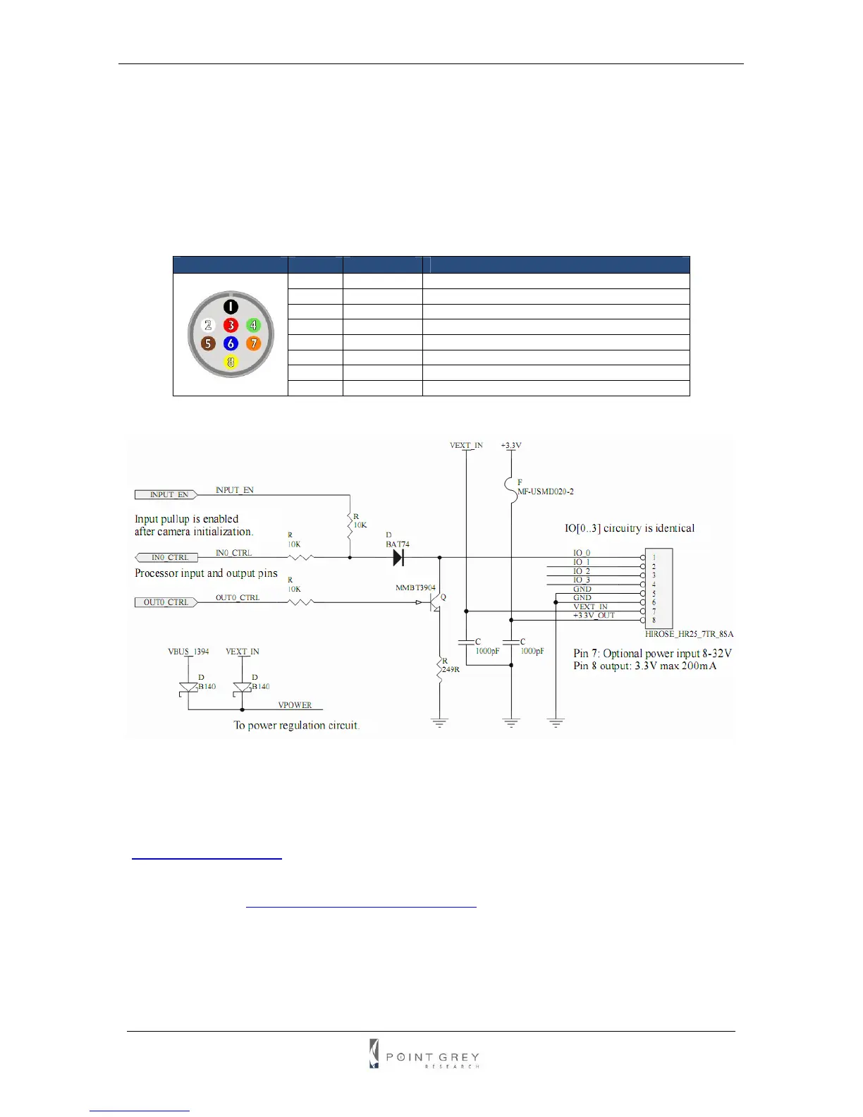
3.5. General Purpose Input/Output (GPIO)
The Grasshopper has an 8-pin GPIO connector on the back of the case. The connector is a
Hirose HR25 8 pin connector (Mfg P/N: HR25-7TR-8SA). KIT contents include a prewired male
connector; refer to the diagram below for wire color-coding. Additional male connectors (Mfg P/N:
HR25-7TP-8P) can be purchased from Digikey (P/N: HR702-ND).
Diagram Pin Function Function
1 IO0 Input / Output (default Trigger_Src)
2 IO1 Input / Output
3 IO2 Input / Output / RS232 Transmit (TX)
4 IO3 Input / Output / RS232 Receive (RX)
5 GND
6 GND
7 V
EXT
Allows the camera to be powered externally
8 +3.3V Power external circuitry up to 150mA
Table 2: GPIO pin assignments
Figure 3: GPIO schematic
Inputs can be configured to accept external trigger signals. Outputs can be configured to send
an output signal, strobe, or PWM signal. To use the RS232 functionality, a level converter must
be used to convert the TTL digital logic levels to RS232 voltage levels. B&B Electronics
(
http://www.bb-elec.com/) part number 232LPTTL can be used for this conversion.
For more information on using the RS232 serial port, download Technical Application Note
TAN2004001 from
www.ptgrey.com/support/downloads/.